
Introduction
SRE is built from two types of nodes: Element Managers, which hold the master database and manage the platform, and Call Processors, which handle the traffic. Call Processors work on a local copy of the data, so the platform keeps processing calls when an Element Manager, a Call Processor or a complete data centre fails. Capacity grows by adding Call Processors. The SRE Product Description explains why the platform is designed this way.
This document describes what runs where, how data reaches the Call Processors, what happens on each type of failure, and how the platform is scaled, upgraded, protected against overload and deployed. It ends with a two-data-centre example.
Architecture
Element Managers
A platform normally has two Element Managers, one active and one standby. The Element Managers provide:
- the GUI and the provisioning REST API;
- the master database, holding the data models and their data, the service logics, the system configuration and the user accounts;
- the collection of CDRs, logs, statistics and alarms sent by the Call Processors.
The Element Managers are not in the call path: calls are processed entirely by the Call Processors.
Call Processors
Call Processors handle the SIP, ENUM and HTTP requests. Each Call Processor runs:
- the SIP stack, which receives the SIP requests from the network;
- a broker, which spreads the requests over the service logic workers. One worker process runs per vCPU, each with several threads;
- a local copy of the database, used for all reads during service logic execution;
- a SIP agents monitor, which probes the SIP peers (see SIP Agent Monitoring and Failover);
- a health monitor, which reports the status of the node to the Element Managers.
All processes are supervised and restarted automatically if they stop. The GUI shows for each node when it was last seen, its processes and its database replication state.
When media services are used, Call Processors are complemented by media servers controlled by SRE.
How Data and Configuration Reach the Call Processors
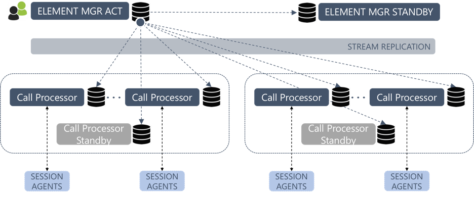
All persistent information is stored in the master database on the active Element Manager: data model records, service logics and their releases, SIP agents, system settings, and so on. This database is replicated to the standby Element Manager and to the local database of each Call Processor using PostgreSQL streaming replication. Each node replicates directly from the master; there is no cascading.
As a result, a data change, a service logic release or a settings change reaches every Call Processor through replication and applies to the next call. A Call Processor reads only from its local copy: service logic queries do not cross the network to the Element Manager.
When a service logic writes data, using the Create database records, Update database records or Delete database records nodes, the write is sent to the REST API of the Element Managers, applied to the master database and then replicated back to all Call Processors.
Accounting events are written to local files on the Call Processor and forwarded to the CDR collector on the master Element Manager. If no Element Manager can be reached, the files are kept and sent once one is available again.
Replication is monitored: alarms are raised when a node disconnects from replication and when the replication lag exceeds configurable thresholds.
Call Admission Control Data
Call admission control counters are shared between Call Processors in real time. It has an odd number of members, for example three Call Processors, or two data nodes plus an arbiter on the standby Element Manager, and remains available as long as a majority of members is up.
Failure Scenarios
Call Processor Failure
Call Processors are self-contained, so the loss of one does not affect the others. The SIP clients (SBCs, softswitches) are configured with several Call Processors and send traffic to the remaining ones. Call Processors answer SIP OPTIONS, so SIP clients can probe them to detect a failure.
Optionally, Call Processors can be grouped in pairs with Pacemaker. A virtual IP address and its SIP stack then move to the second Call Processor of the pair when the first one fails, so the SIP clients keep using the same address.
Element Manager Failure
When the active Element Manager fails, the Call Processors keep processing calls on their local copy of the data. What is temporarily lost is the ability to provision, to change the configuration and to write data from the service logic until a master database is available again.
Since SRE 4.0, the database switches over automatically. A replication manager runs on each node and, when the master database is lost, promotes the standby Element Manager to master. The Call Processors' local databases are then redirected to follow the new master. Alarms are raised on switchover and on changes of the replication manager state. Automatic switchover is enabled by default and can be paused, for example before rebooting the master for maintenance.
Since SRE 4.1, an operator can also trigger the switchover from the GUI: the Promote current node action, available on the Node Operational Status page of the standby Element Manager, promotes it to master and instructs all other nodes to follow it. This is useful for planned maintenance of the master Element Manager.
After a switchover, the former master is rejoined as a standby, as described in the OAM Guide. Since SRE 4.1, database backups are also synchronised to the standby Element Manager.
Data Centre Failure
When the nodes are spread over two data centres, the loss of one combines the two cases above: the surviving Call Processors keep processing calls, and the standby Element Manager is promoted if the master was in the lost data centre. The Example: Two Data Centres section describes this step by step.
Data Versions and Table Synchronisation
Independently of the replication between nodes, each data model is stored in two versions, A and B, one active and one standby, as explained in the Data-Driven Call Handling feature description. Since SRE 4.1, the operator can copy a table from one version to the other, in either direction, from the System / Data Versioning menu.
SIP Agent Monitoring and Failover
SRE monitors the availability of its own SIP peers (SBCs, media servers, carriers, PBXs) so that the service logic can route around a failed one.
- Probing: each Call Processor sends SIP OPTIONS to the SIP agents configured in System / SIP Agents Monitoring, at a configurable interval. Probing is available over UDP and TCP, over TLS since SRE 4.1 and over SIPS since SRE 4.2. Each agent is reported as UP, DOWN or TRYING, and alarms are raised when an agent goes down or stops answering.
- Using the status: the SIP agent status node branches the service logic depending on whether a destination is up or down, so a call is only sent to a destination that is up.
- Crankback: the SIP Relay node can re-run the service logic when the destination returns a SIP error, for example 503 Service Unavailable. With the call descriptor persisted between iterations, the next route in a list retrieved from the database is used without repeating the queries. Since SRE 4.1, the contacts of a 3xx redirect response are also available to the service logic.
Scaling
Adding Call Processors
SRE scales horizontally. Adding capacity means adding a Call Processor: the new node is installed, clones the database from the master Element Manager, registers with the replication cluster and starts receiving updates. The SIP clients are then configured to send traffic to it. The number of worker processes on a Call Processor follows the number of vCPUs, so a node can also be scaled vertically.
Upgrades
Hitless and Rolling Upgrade
Since SRE 4.0, the SIP stack of a Call Processor can redirect its traffic to another Call Processor, after checking that the target is alive. While the software on the first Call Processor is upgraded or restarted, its SIP stack keeps receiving requests on the same address and forwards them for processing, so SIP clients see no change.
Manual Upgrade and Downgrade
Upgrades can also be performed manually, in the same order, verifying on the first upgraded Call Processor that calls and CDRs are handled as before. A Call Processor can be put out of service from the Node Operational Status page; it then answers INVITE and OPTIONS requests with 503 Service Unavailable so that the SIP clients move its traffic elsewhere.
A patch release is rolled back by reinstalling the previous package. Rolling back to a previous major release also requires downgrading the database schema on the master Element Manager and restoring the previous SIP stack configuration on the Call Processors. The release notes of each version describe the exact steps.
Overload Protection
Several mechanisms protect the platform during overload:
- Service logic execution deadline: since SRE 4.1, each request carries a deadline based on the configured request timeout. If the service logic has not finished by then, its execution is stopped, since the caller would ignore a late answer anyway, and the request is answered with an error. This frees the workers during overload.
- Rate limiting: since SRE 4.1, an optional rate limit module can be enabled in the SIP stack configuration.
- Licence limits: requests above the licensed capacity are rejected with 503 Service Unavailable, as described in Licensing.
- Alarms: on CPU, memory and disk usage, on request processing time, on licence limits and on SIP stack memory. Since SRE 4.2, the SIP stack receive queue (to detect exhausted workers) and private memory are also monitored.
Deployment Options
The same architecture applies to all deployment options:
- Virtual machines or COTS servers running RHEL 8 or 9, with Element Managers and Call Processors on separate machines. A standalone installation, with both roles on one machine, is possible for labs.
- Docker (since SRE 4.1): an official all-in-one image includes SRE and the third-party software it needs, such as the database and the SIP stack. The same image is started as an Element Manager or a Call Processor depending on its options, so the two-Element-Manager, multi-Call-Processor design is kept.
- Kubernetes (since SRE 4.2): a Helm chart deploys SRE with a SIP load balancer in front of the Call Processors. The number of call, HTTP, ENUM and media processors is set as a parameter, and the database is provided by a PostgreSQL operator with separate read/write and read-only endpoints.
- SREaaS: the platform is operated by Netaxis, as described in the SRE Product Description.
The Installation Guide, the Container Deployment Guide and the Kubernetes Deployment Guide describe each option.
Example: Two Data Centres
A service provider runs SBCs in two data centres, DC1 and DC2, and wants to keep full service if either data centre is lost. It deploys SRE in N+1 mode across both sites:
| Node | DC1 | DC2 |
|---|---|---|
| Element Manager | EM1 (active, master database) | EM2 (standby) |
| Call Processors | CP1, CP2 | CP3, CP4 |
| Call admission control | MongoDB member on CP1 | MongoDB members on CP3 and EM2 (arbiter) |
The Call Processors of each site are dimensioned so that one site alone can carry the peak traffic. The SBCs of both sites are configured with all four Call Processors, preferring the local ones, and probe them with OPTIONS. All Call Processors replicate from EM1 and probe the same SIP agents.
In normal operation, provisioning is done on EM1 and replicated to the four Call Processors.
DC1 then loses power:
- CP1 and CP2 stop answering. The SBCs in DC2 see their OPTIONS fail and send all traffic to CP3 and CP4. Calls are processed with the data already present in their local copies.
- The replication manager detects that the master database is gone and promotes EM2 to master. CP3 and CP4 now follow EM2, and a database switchover alarm is raised.
- Provisioning through the GUI and REST API resumes on EM2. Service logic writes and CDRs are sent to EM2.
- The SIP agents in DC1 no longer answer the OPTIONS sent by CP3 and CP4 and are no longer reported UP. Service logics that check agent status or use crankback route calls to destinations in DC2.
- Call admission control remains available, since two of the three replica set members are in DC2. Had DC2 been lost instead, the majority would have been lost; placing the third member in a third location avoids this.
When DC1 comes back, EM1 is rejoined as standby of EM2, CP1 and CP2 are re-synchronised with the new master, and the SBCs return traffic to them once they answer OPTIONS again. If preferred, EM1 is later made master again with a manual switchover from the GUI.