What's new / changed in SRE 3.3
This section presents the list of locations that have been added or modified concerning new/changed features in SRE 3.3 Release.
It allows users familiar with earlier releases to jump directly to these locations.
WARNING
The section below provides working links to new/changed sections or locations in this Nodes Description Manual document only.
A similar section can be found in Service Logic Editor Manual and SRE Admin Guide documents, with working links to the targeted sections/locations. You will need to open the other documents and look for their What's new in 3.3 own section to use active links.
New / changed in this Nodes Description Manual
- New node: custom Response Code and Reason header See Custom SIP Response - new in 3.3
- New node to check if a specific alarm is active or not See Alarm conditions - new in 3.3
- New node to perform regexp extraction from SIP payload See SIP regular expression extraction - new in 3.3
- New node to rotate a List of Records See Rotate list of records -- new in 3.3
- Modified node: Extract SIP headers to a List of Records or plain variables See Extract SIP headers
- Nodes to JSON encode and decode data structures (lists of records) See Convert list of records to JSON object - new in 3.3 and Convert JSON object to list of records - new in 3.3
- Add operation on List of records / Aggregate column node: count records See Aggregate Column - changed in 3.3
- Add option "if not set" to node Set variables See Set variables - changed in 3.3
- Improved logging for external query nodes See Improved logging -- new in 3.3
- Nodes to encode, decode, validate JWT (Json web token) See Encode JWT, Decode JWT, Validate JWT
- Nodes to generate, extract, add the identity header to implement STIR/SHAKEN See Generate Identity header, Extract Identity header, Add Identity header
Nodes Description
Processing Nodes
SRE Processing Nodes are categorized as follows. Click any link to jump to its content.
- Manipulation
- Extraction
- List of records
- Flow control
- Database
- Caching
- External query
- Date & time
- URI
- SIP
- Stir/Shaken
- Accounting
- Call Admission Control
- Misc
Placeholder mechanism
Some fields in some nodes admit placeholders instead of values.
The placeholder [calling] is replaced with the value of the variable calling in the Call Descriptor.
Placeholders are valid for fields in Table 1 below. In a Call Descriptor, there are predefined variables (see Table 2](#table-2)below) and variables dynamically created by nodes such as 'set variable' or 'create list of records'. Placeholders are applicable to all variables: predefined and created by previous nodes.
In the SLE, only a subset of predefined variables is available for Simulate Call.
INFO
If a node sets a variable with the name of an existing variable, the existing variable is lost. For example, if a new variable is called 'destinationAddress', the previous content of this variable that comes from the SIP message is replaced.
Table 1
| Nodes | Fields |
|---|---|
| Set variables | Value |
| HTTP JSON request | Body, URL |
| HTTP XML request | Body, URL |
| LDAP query | Filter |
| Nemo QoS | Nemo stats API URL endpoint |
| Send syslog message | Message |
| Send Email | Subject, Message |
| Append row to list of records | Value |
| Create list of records | row fields |
Table 2
| Predefined variables | SIP Call | Simulation SIP | Simulation Call |
|---|---|---|---|
| callId | X | X | X |
| called | X | X | X |
| calling | X | X | X |
| counter | X | X | X |
| destinationAddress | X | X | |
| destinationPort | X | X | |
| fromURI | X | X | |
| fromUsername | X | X | |
| lastCode | X | ||
| lastRequestURI | X | ||
| originalCalled | X | X | X |
| originalCalling | X | X | X |
| requestMethod | X | X | |
| requestURI | X | X | |
| requestUsername | X | X | |
| sourceAddress | X | X | |
| sourcePort | X | X | |
| toURI | X | X | |
| toUsername | X | X | |
| ssCode [^1] | X | ||
| ssAttestation [^2] | X | ||
| ssOrigin [^2] | X | ||
| ssDestination [^2] | X |
[^1]: This is set to 2 if stir/shaken verification is not enabled, 0 if stir/shaken check was successful. Otherwise see here for error code values.
[^2]: if ssCode variable is not 0, variable is empty
Manipulation
Digits manipulation
Description: Remove and/or add digits from/to the provided digit string
Fields:
- Node name: name for this node, showing in the node label in the service logic Build grid
- Description: any additional information, showing below the node name label in the service logic Build grid.
- Variable : name of the Call Descriptor variable of which the node will process the value. A click in the field displays the list of available variables. If no Store into field is available, the result is stored in the variable itself, not in another (output) variable.
- Remove digits : removes n digits from the value, starting at defined position.
- Insert digits : inserts n digits into the value, before the defined position (position 1 means « insert before pos. 1 ».
Regular expression substitution
Description: Find and replace a substring into the provided string using regular expressions and store the result in a variable
Fields:
- Node name: name for this node, showing in the node label in the service logic Build grid
- Description: any additional information, showing below the node name label in the service logic Build grid.
- Regular expressions substitutions: to substitute substrings in the selected value with the results of one or more regular expressions and to store the output in the value selected in the Store result into field. The regular expression defined in Reg Expression field is a search (finding substrings), not a match:
abc([0-9]*)defwill process456from input123abc456def123as well as fromabc456def. Successive substitutions are allowed. The variable selected as output can be re-used as input for another substitution. Overwriting the input value with the output value in the same variable is also allowed. It is advisable to test the regular expression(s), using for example regexp101.com.
Set variables - changed in 3.3
Description: sets one or more variables
Fields:
- Node name: name for this node, showing in the node label in the service logic Build grid
- Description: any additional information, showing below the node name label in the service logic Build grid.
- Variables : to add one or more new variables to the Call Descriptor. Valuefield can be either an existing value (from the list) or a string. Placeholders (
[variable_name])are allowed: for a new variable namedmy_var, the input of Valuethis is the calling number: [calling]will store intomy_varthe text « this is the calling number: » and the value of thecallingvariable. See Placeholder mechanism for more information. - If not set: if checked, will set the variable only if has not been set previously. If unchecked, will overwrite the current value of the variable if already set previously.
Unset variables
Description: unsets one or more variables
Fields:
- Node name: name for this node, showing in the node label in the service logic Build grid
- Description: any additional information, showing below the node name label in the service logic Build grid.
- Variables : to unset (or delete) one or more variables within the Call Descriptor.
Map Value
Description: Sets or changes the value of a variable depending on its current value. It allows for different possible mappings, in a sequential way.
Fields:
- Node name: name for this node, showing in the node label in the service logic Build grid
- Description: any additional information, showing below the node name label in the service logic Build grid.
- Variable name: the name of the variable that one wants to replace
- Mappings > Source value: the possible current value of the variable. Can be another referenced variable
- Mappings > Mapped value: the new value that the variable will assume if at the moment of checking it has the value in "Source value"
- Store into: the name of the target variable to be created/overwritten with the mapped data (leave empty to modify original variable)
Concatenate
Description: Concatenate several variables/strings into a single string and store the result in a variable
Fields:
Node name: name for this node, showing in the node label in the service logic Build grid
Description: any additional information, showing below the node name label in the service logic Build grid.
Elements : one or more elements (string or existing variable name) to concatenate
Store into : the name of the target variable (existing or new) where the output of the operation will be stored.
INFO
The same result for more than one variable can be achieved using the Set variables - changed in 3.3 node.
Reverse
Description: Reverse the characters of the provided string and store the result in a variable
Fields:
- Node name: name for this node, showing in the node label in the service logic Build grid
- Description: any additional information, showing below the node name label in the service logic Build grid.
- Variable : name of the Call Descriptor variable of which the node will process the value. A click in the field displays the list of available variables. If no Store into field is available, the result is stored in the variable itself, not in another (output) variable.
- Store into : the name of the target variable (existing or new) where the output of the operation will be stored.
Extraction
Digits extraction
Description: Extract some digits from the provided digit string and store them in a variable
Fields:
- Node name: name for this node, showing in the node label in the service logic Build grid
- Description: any additional information, showing below the node name label in the service logic Build grid.
- Extract digits : to set the variable(s) to extract digits from, to define the substring to extract (Start Index and Extraction length) and to set the target (existing or new) variable(s) (Store into)
Regular expression extraction
Description: Extract a substring from the provided string based on a regular expression with regex capturing groups and store the result in a variable
Fields:
Node name: name for this node, showing in the node label in the service logic Build grid
Description: any additional information, showing below the node name label in the service logic Build grid.
Regular expressions extractions :
- Reg expression : the reg expression to use to extract a substring. Regex capturing group(s) are valid: example highlighted in blue in the screenshot below.
- Variable to match : the existing variable to extract the substring from.
- Group to extract : the sequence number of the capture group defined in Reg expression, NOT prefixed with a \ as this is not a substitution.
- Store result into: the target variable (new or existing) for this extraction.
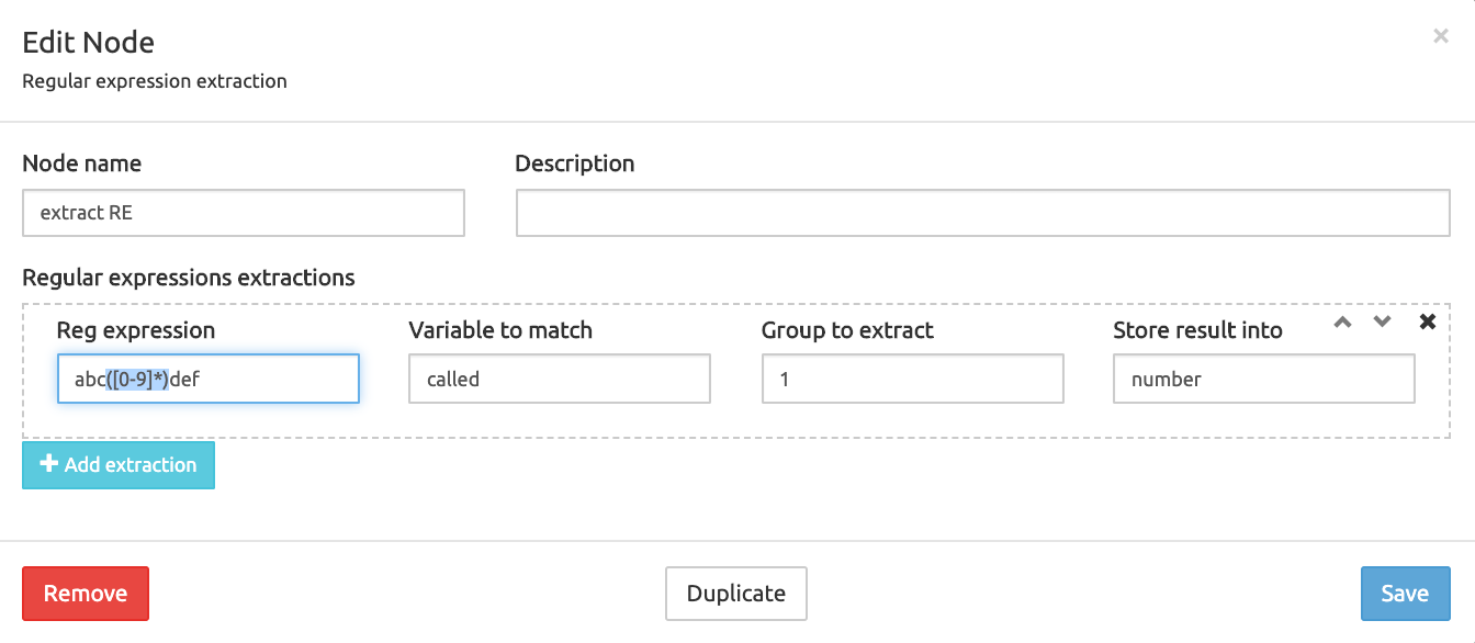
Successive extractions are allowed. The variable selected as output can be re-used as input for another extraction. Overwriting the input value with the output value in the same variable is also allowed.
INFO
The same result (extracting a substring using a regexp capture group and storing it into a new variable) can be achieved using the Regular expression substitution node.
List of records
Create list of records
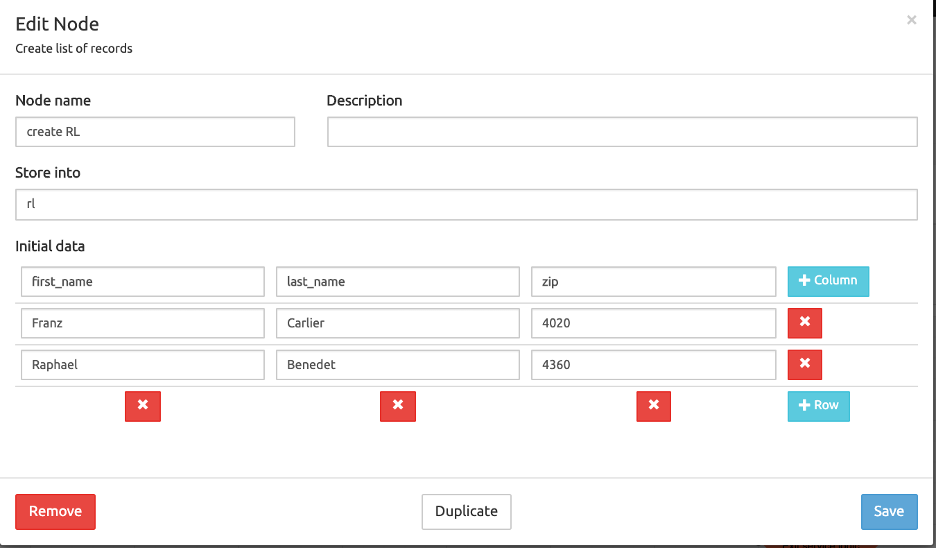
Description: defines a static records list with multiple rows and columns
Fields:
Node name: name for this node, showing in the node label in the service logic Build grid
Description: any additional information, showing below the node name label in the service logic Build grid.
Store into : the name of the target record list to be created with the initial data defined below
Initial data : to create the columns and rows of the record list to be created Columns are defined as the first row below Initial data and become headers. The next row(s) have the data.
Convert list of records to JSON object - new in 3.3
Description: Converts internal data structures (a list of records) to a JSON object.
Fields:
- Node name: name for this node, showing in the node label in the service logic Build grid
- Description: any additional information, showing below the node name label in the service logic Build grid.
- Read from: a list of records created beforehand by a Create LoR node (see above).
- Store into: a name for the JSON object to create
Convert JSON object to list of records - new in 3.3
Description: Converts a JSON object into an internal data structure (a list of records).
Fields:
- Node name: name for this node, showing in the node label in the service logic Build grid
- Description: any additional information, showing below the node name label in the service logic Build grid.
- Read from: a JSON object created beforehand, possibly by a Convert LoR to JSON node above.
- Store into: a name for the list of records to create
Append row to list of records
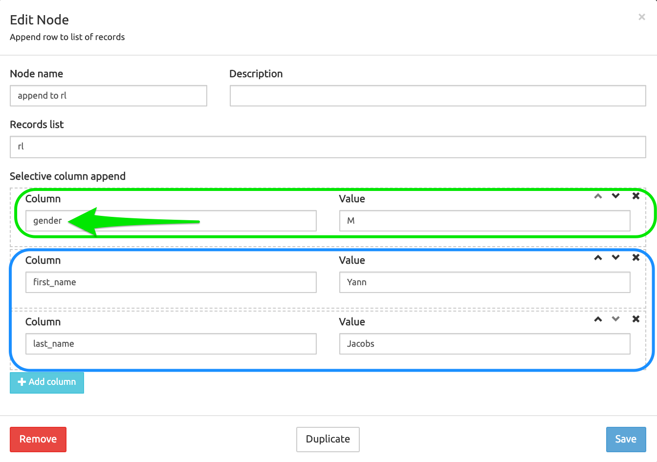
Description: appends a row with values or a new column with a value to an existing records list
Fields:
Node name: name for this node, showing in the node label in the service logic Build grid
Description: any additional information, showing below the node name label in the service logic Build grid.
Records list : the source list of records to be processed
Selective column append : adds a new column with new data to the records list (in green below) or a row with new data in existing columns (in blue below)
Filter rows from list of records
Description: filters the rows from a list of records based on conditions
Fields:
Node name: name for this node, showing in the node label in the service logic Build grid
Description: any additional information, showing below the node name label in the service logic Build grid.
Records list : the source list of records to be processed
Filter : to decide whether rows matching the conditions (defined below) are included (only matching rows are kept, non-matching rows are excluded) or excluded (only non-matching rows are kept).
True if : defines the combined logic applied to the conditions groups (OR / AND)
Condition groups : one or more groups of one or more conditions applied to the source record list The local True if allows defining a combined logic to apply to the conditions within the group.
Store manipulated records list into : the target list of records where to store the result of the applied filter. If left blank, the source list of records is overwritten with the result. In the screenshot below, the source (Records list)is
rland the target (Store manipulated... into)flr.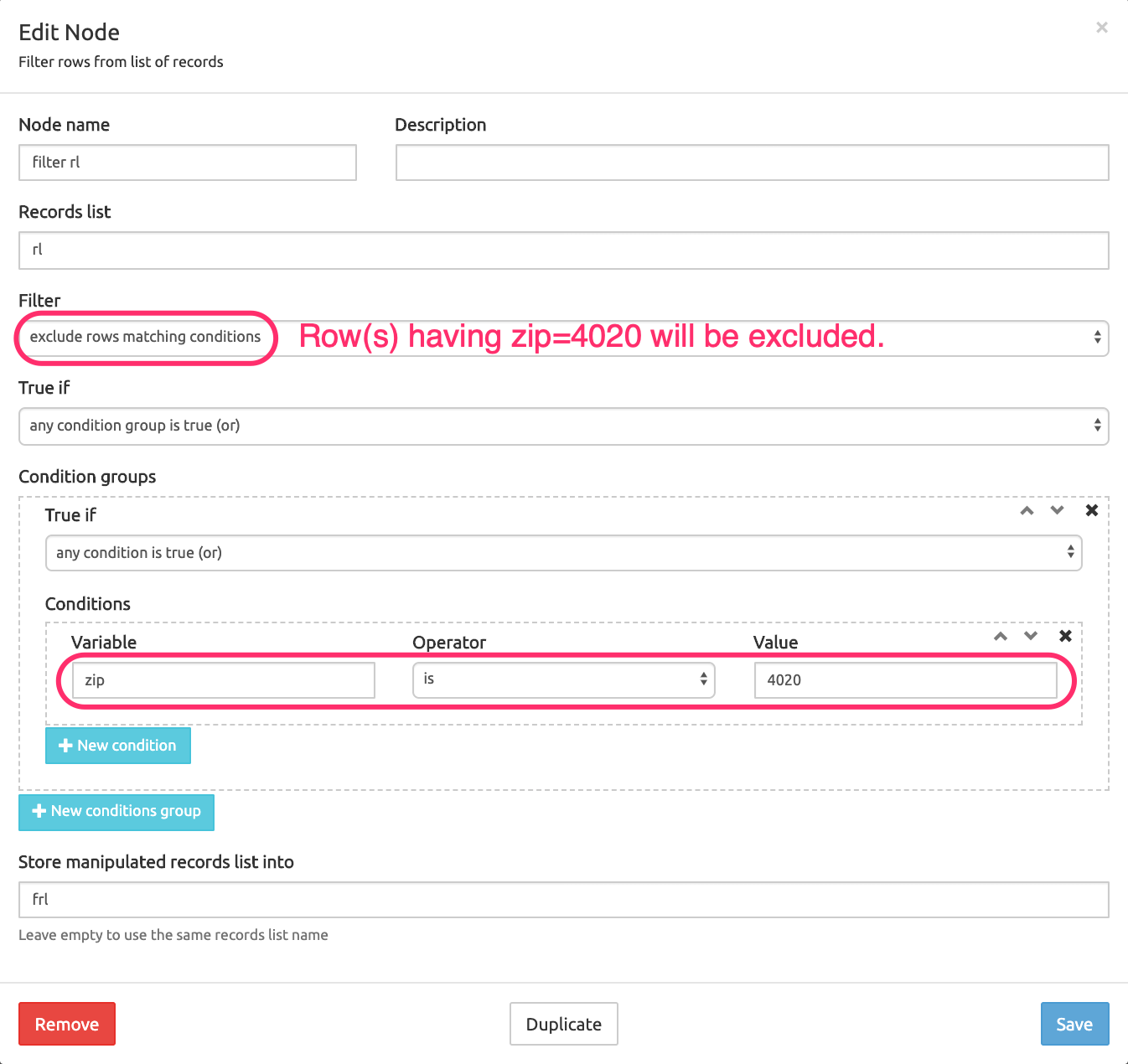
The screenshot below shows the Call Descriptor (in Simulate Call tab after a run) after filtering the source records list as shown above.
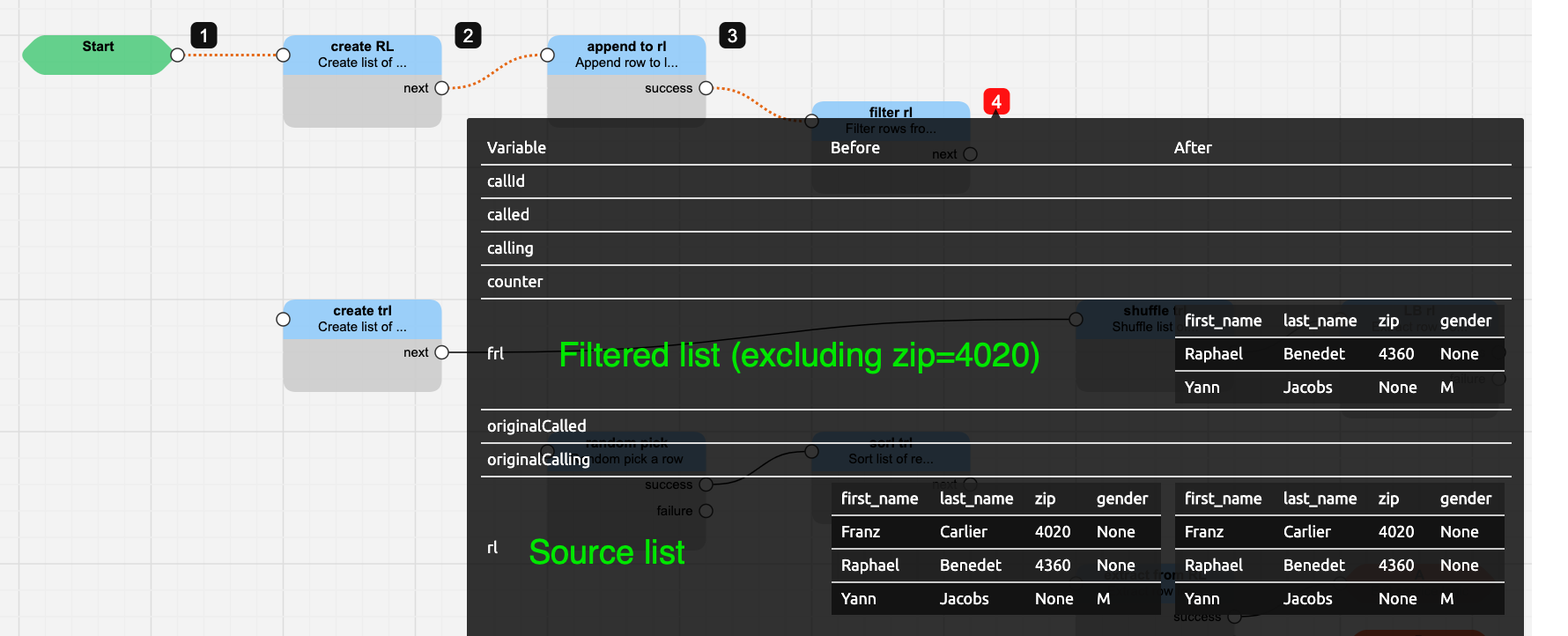
The Simulation line at the bottom of the grid is another way to view how the data have been processed during the execution of the whole service logic. For an example, see the Simulation Line screenshot in the section below.
Extract row from list of records
Description: picks one row from an existing records list and saves its values into variables
Fields:
Node name: name for this node, showing in the node label in the service logic Build grid
Description: any additional information, showing below the node name label in the service logic Build grid.
Records list : the source list of records to be processed
Row selected : the row to pick: First, Last, Random or Index
Extract row index : the position of the row to pick from the list (the index start at zero [1 selects the second line]).
Remove row : removes the selected row from the source record list
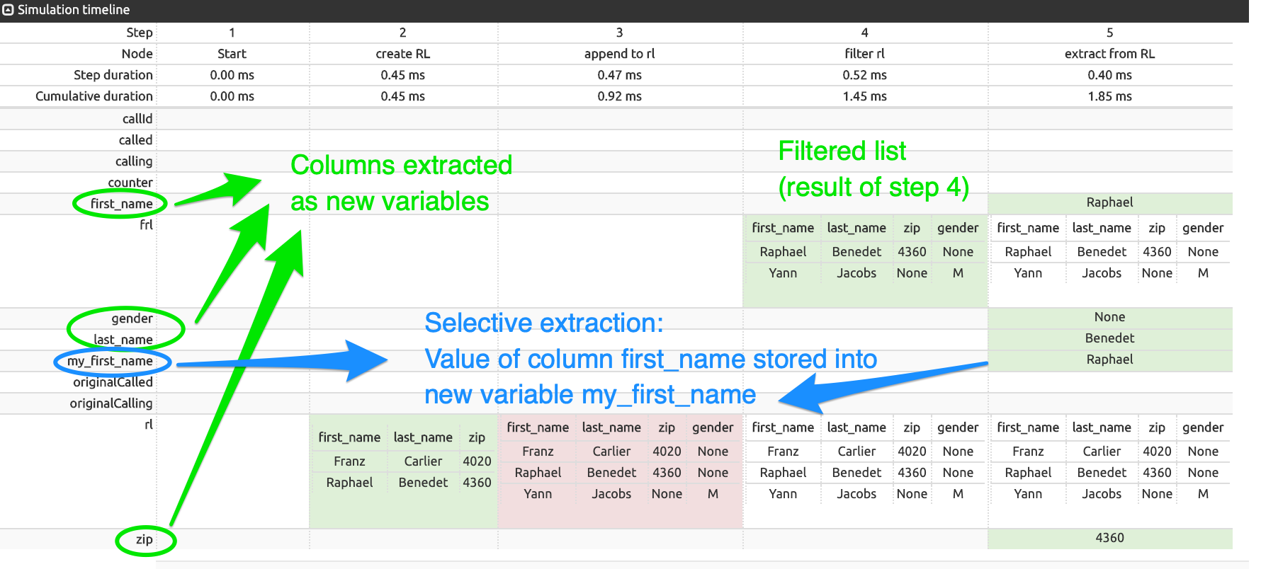
Extract columns into respective variable names : adds each column as a new variable in the Call Descriptor (see first screenshot below)
Selective column extraction : stores the value of the selected row and column into the new variable defined.
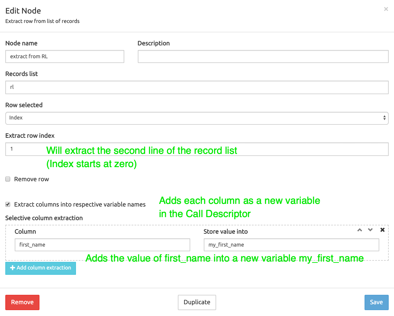
Resulting simulation line:
Random pick a row
Description: randomly picks a row from a records list, optionally weight-based
Fields:
Node name: name for this node, showing in the node label in the service logic Build grid
Description: any additional information, showing below the node name label in the service logic Build grid.
Records list : the source list of records to be processed
Column with weight : random picking probability can be affected by assigning a weight to entries in the record list. In the example below, a column
weighthas been defined for the list, with values 4, 4, 10.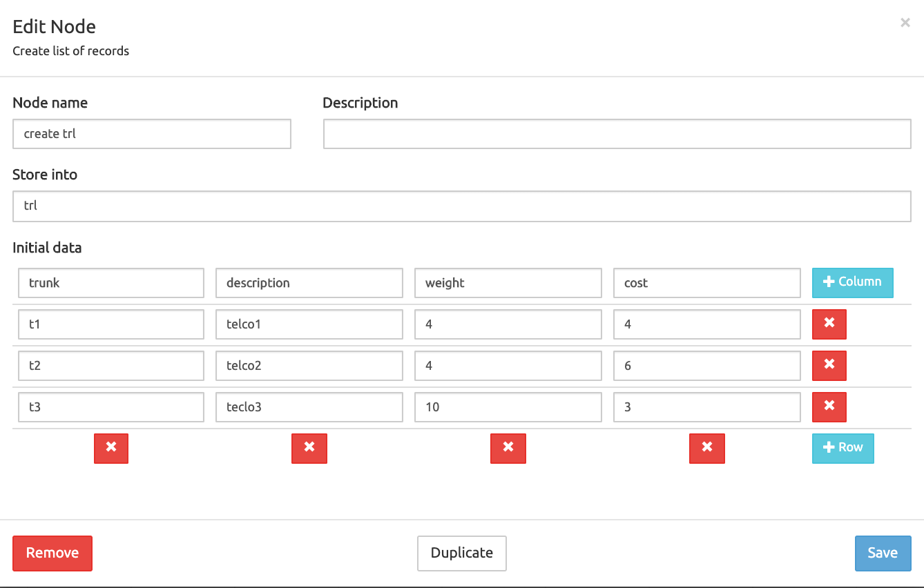
If the column
weightis selected in Column with weight as below, this has the effect that over 18 runs of the Randow pick node, valuest1andt2will be picked 4 times each, while valuet3will be picked 10 times.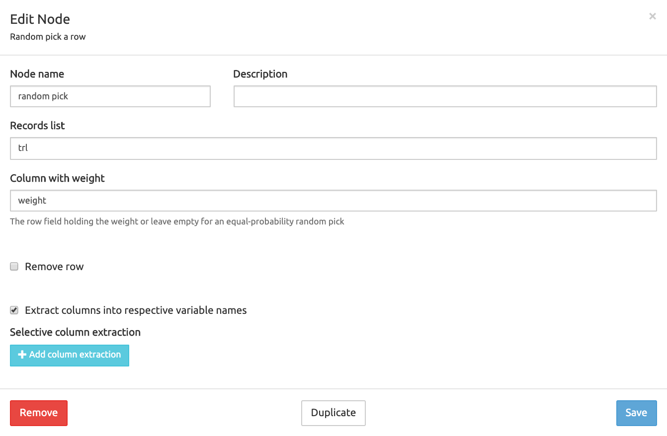
Remove row : removes the selected row from the source record list
Extract columns into respective variable names : adds each column as a new variable in the Call Descriptor (see above)
Selective column extraction : stores the value of the selected row and column into the new variable defined (see above) Resulting simulation line : the 3rd row with
weight = 10has been picked and each value of each column for this row has been extracted to a new variable named after the column header (green values in step 3).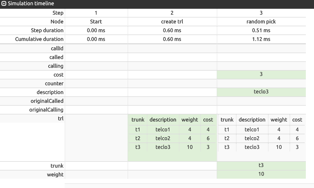
Sort list of records
Description: sorts a record list based on the values in one or several columns
Fields:
Node name: name for this node, showing in the node label in the service logic Build grid
Description: any additional information, showing below the node name label in the service logic Build grid.
Records list : the source list of records to be processed
Sort rows : to select column(s) to use as ascending or descending sorting key(s)
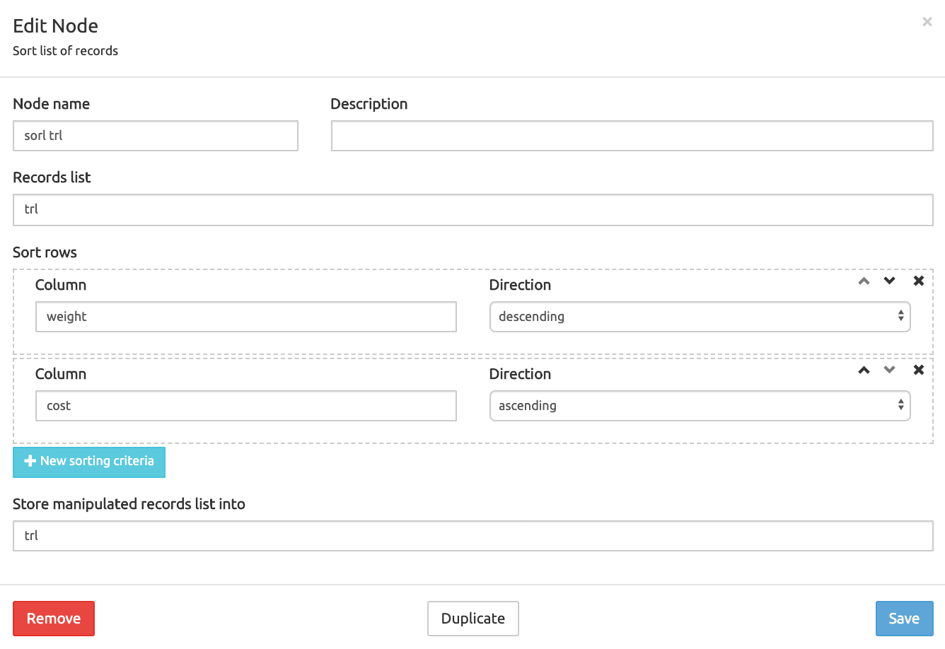
Store manipulated records list into : target record list to store the sorted list. Using the value given above as (source) Records List overwrites the source list.
Shuffle list of records
Description: using as seed a given Call Id from a SIP INVITE, shuffles the rows of source records list into a stable records list usable in crankback situations.
For example, a service logic will manage an error after sending a SIP message to a trunk by re-sending the same message (based on identical Call ID) to the second or third trunk of a shuffled records list of 3 trunks.
INFO
Simulations of a service logic using this node MUST be launched from the Simulate SIP tab, as an INVITE having a Call ID is expected to process the source records list.
Fields:
- Node name: name for this node, showing in the node label in the service logic Build grid
- Description: any additional information, showing below the node name label in the service logic Build grid.
- Records list : the source list of records to be processed
- Store manipulated records list into: target record list to store the sorted list. Using the value given above as (source) Records List overwrites the source list.
Aggregate Column - changed in 3.3
Description: allows calculating the values of a specific column for entries in a record list
Fields:
Node name: name for this node, showing in the node label in the service logic Build grid
Description: any additional information, showing below the node name label in the service logic Build grid.
Records list : the source list of records to be processed
Store results into: target variable to store the computed operation output. The output is a variable and not a record list.
Column: the column in the record list that is subject to the chosen calculation
Operation: available operations are:
- sum
- minimum
- maximum
- average
- count (new in 3.3)
Rotate list of records -- new in 3.3
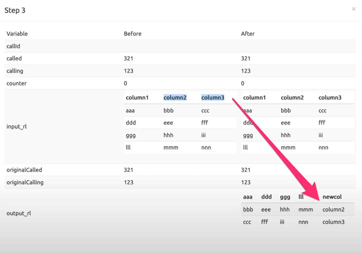
Description: Rotate a list of records by swapping rows and columns. Data from the column selected in the source List of records become column headers in the resulting rotated list.
Fields:
Node name: name for this node, showing in the node label in the service logic Build grid
Description: any additional information, showing below the node name label in the service logic Build grid.
Records list : the source list of records to be processed
Store results into: name for the resulting list after execution
Column to use for new column headers: data in this column become the column headers of the resulting list.
The image below shows the Call Descriptor of the node after execution. Data in the source column1 become column headers in the resulting list.
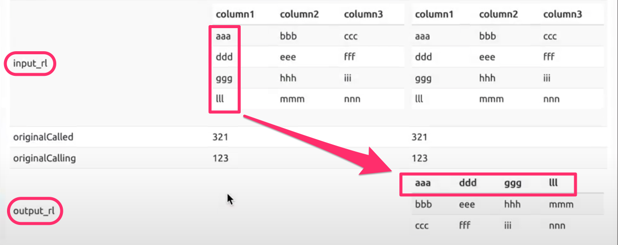
Move current column headers to new column: name of an additional column storing the column headers of the source list (except the header of the selected «column to use») in the resulting list. If left empty, original headers are not kept (as in the image above).
The image below shows the resulting list with the original column headers preserved in newcol.
Flow control
Flow Control nodes allow managing conditions.
Conditions are defined through a variable, an operator and a value (var_a starts with 02). However, a variable is allowed as the value in some nodes, according to the table below. See Manipulation, Set variables - changed in 3.3 for more details.
Flow Control nodes Variables allowed
Digits analysis - Combined conditions yes Combined condition groups yes Sequential conditions yes Days conditions - Load balance yes (weight) Regular expression match - Audio Codec decision -
Audio Codec decision
Description: Connect to different service logic branches based on the presence of a certain media codec in the SDP of the incoming SIP message. This message should be provided in the SIP Message field of the Simulate SIP tab.
Fields:
Node name: name for this node, showing in the node label in the service logic Build grid
Description: any additional information, showing below the node name label in the service logic Build grid.
Read From Record List: a record list with potential matching codecs.
Audio Codecs: one or more codecs to select the appropriate service branch. The list of available codecs can be found here: https://www.iana.org/assignments/rtp-parameters.
- next node for codec 1, codec 2, etc.
- Fallback: if no matching codec is found in the list.
Digit analysis
Description: Create a digit map for a variable and a set of possible values (digits) and connect to different service logic branches depending on the most significant digits of the NA which is subjected to the analysis. If none of them is matched, a fallback output is provided.
Fields:
- Node name: name for this node, showing in the node label in the service logic Build grid
- Description: any additional information, showing below the node name label in the service logic Build grid.
- Variable: the name of the variable to be tested
- Selections: the set of values to be tested
- Digits: first, second, and third value for the variable
- Output
- jump to: next nodes when variable = digit 1, digit 2, etc.
- fallback: next node if the variable does not match any of the digit values defined.
Combined conditions
Description: Create a simple condition or a logical combination of several conditions and connect to different service logic branches depending on whether or not the combined conditions are met.
The underlying syntax is: cond_1 op cond_2 op ... op cond_n with op = and/or
Fields:
Node name: name for this node, showing in the node label in the service logic Build grid
Description: any additional information, showing below the node name label in the service logic Build grid.
True if: logical test. True if any of the conditions is met (OR) or all conditions are met (AND)
Conditions : one or more conditions with variable, operator and value. Several conditions are logically combined along with the True if test (AND / OR).
Available operators :
- exists (no value required)
- does not exist (no value required)
- is
- is not
- contains
- does not contain
- starts with
- does not start with
- ends with
- does not end with
- is greater or equal to
- is greater than
- is less than or equal to
- is less than
- length is
- length is not
- length is greater or equal to
- length is greater than
- length is less than or equal to
- length is less than
- matches regular expression
- does not match regular expression
Output
- true: when all condition expression is true
- false: when all condition expression is false
Combined condition groups
Description: Create a logical combination (AND/OR) of several conditions between blocks of conditions and connect to different service logic branches depending on whether or not the combined conditions are met.
The underlying syntax is:
- For the group of conditions: group_1 op1 group_2 op1 ... op1 group_n with op1 = and/or
- For the conditions:
within a group : cond_1 op2 ... op2 cond_m with op2 = and/or
Fields:
Node name: name for this node, showing in the node label in the service logic Build grid
Description: any additional information, showing below the node name label in the service logic Build grid.
True if: logical tests for the condition groups and for the conditions:
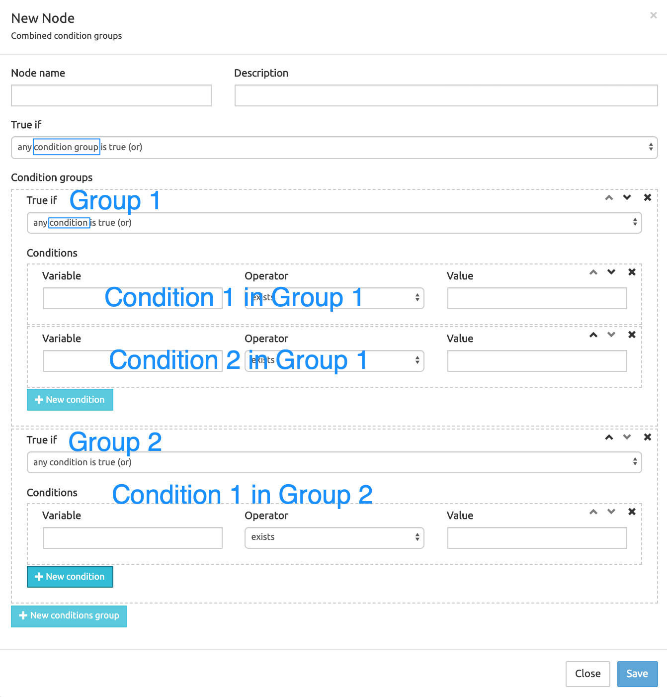
Condition groups: several groups of one or more conditions with variable, operator and value. Conditions within a group then condition groups are logically combined along with the True if tests (AND / OR).
Output
- true: when all condition expression is true
- false: when all condition expression is false
Sequential conditions
Description: Create a set of simple conditions that are tested sequentially until one condition is met.
Fields:
Node name: name for this node, showing in the node label in the service logic Build grid
Description: any additional information, showing below the node name label in the service logic Build grid.
Conditions : several conditions with variable, operator and value. The process exits when a condition is satisfied. If no condition is met, a fallback is provided.
Output :
- next nodes at exit of condition 1, 2, 3...
- Fallback: next node when no condition is met.
Alarm conditions - new in 3.3
Description: Creates a condition based on an alarm type (see Settings/Alarms, col. Type) and connects to different service logic branches depending on whether or not the alarm is active.
Fields:
- Node name: name for this node, showing in the node label in the service logic Build grid
- Description: any additional information, showing below the node name label in the service logic Build grid.
- Type prefix: the type of an alarm in the Alarm List
- Caching: if the alarm is set and Caching is set to x secs, the SL will check every x secs internally (which means that an alarm just generated may not be picked up immediately).
Days conditions
Description: Create a weekly schedule with one-time frame per day, and connect a different service logic branch depending on whether or not the current time is inside or outside the provided time frame.
Fields:
Node name: name for this node, showing in the node label in the service logic Build grid
Description: any additional information, showing below the node name label in the service logic Build grid.
Hours Conditions: defines a schedule to test if the current time is/is not between time frame 1 (hh:mm) and time frame 2 (hh:mm).
Output :
- exit if match
- exit if not match
Load balance
Description: Distribute traffic over a set of service logic branches in line with the provided weights.
Fields:
Node name: name for this node, showing in the node label in the service logic Build grid
Description: any additional information, showing below the node name label in the service logic Build grid.
Weights: integers to determine how many times an exit node will be selected (pseudo-random).
Weights Selection rate Distribution 5 This weight/total of weights = 50% 5 times over 10 3 This weight/total of weights = 33% 3 times over 10 2 This weight/total of weights = 20% 2 times over 10 Output :
- next node for weight 1, weight 2, etc.
- Fallback: if the value of the selected weight is not an integer.
Regular expression match
Description: Match one or more variables against a regular expression, combine them logically (AND or OR) and connect them to a different service logic branch depending on the outcome.
Fields:
Node name: name for this node, showing in the node label in the service logic Build grid
Description: any additional information, showing below the node name label in the service logic Build grid.
Conditions: one or more conditions testing if the value of the selected variable matches the regular expression
- Regular expression
- Variable to test (can be a variable from the list or any «local» variable defined as explained in Set variables - changed in 3.3.
Conditions logic: if more than one condition is defined, selects the logical test OR (at least one condition matches) or AND (all conditions match).
Output :
- exit node if match
- exit node if no match
SIP agent status
While not being an external query, this node has the same improved logging as described in Improved logging -- new in 3.3.
Description: Check the status of a remote SIP endpoint by specifying its URI and connect to different service logic branches depending whether the endpoint is up or down.
Fields:
- Node name: name for this node, showing in the node label in the service logic Build grid
- Description: any additional information, showing below the node name label in the service logic Build grid.
- Get request URI:
- Outputs:
- If the node is UP then jump to
- If the node is DOWN then jump to
- If the node is TRYING then jump to
Database
Create database record
Description: Contact the SRE REST API to add a new entry to one of the database tables
Fields:
- Node name: name for this node, showing in the node label in the service logic Build grid
- Description: any additional information, showing below the node name label in the service logic Build grid.
- Table: the name of the table where to create a new record
- Fields update: a list of fields with the value each field will take for the new record. A unicity control prevents inserting values already existing for an indexed field, depending on the data model for the table.
- Outputs
- record created: next node
- failure: next node if record creation fails (typically because of an invalid value)
INFO
Creating a record does not affect any variable belonging to the service logic, only fields in the selected database table: no DB record field name or value is visible in the Call Descriptor or Simulation Timeline. The effect of the record creation is visible by refreshing the display of the Data Administration page of the table selected above.
Update database records
Description: Contact the SRE REST API to update one or more existing entries in one of the database tables
Fields:
Node name: name for this node, showing in the node label in the service logic Build grid
Description: any additional information, showing below the node name label in the service logic Build grid.
Table: the name of the table containing the record(s) to update
Filters: field name/operator / value lines to filter the entire record list for selecting one or more records to update. Several filters can be used together and combined with the Conditions logic setting below.
Conditions logic: decides if the update will be executed if any of the conditions (filters) is met (OR) or all must be met (AND)
Fields update: a list of one or more field names, each with its new value.
Outputs
- records updated: next node
- no records updated: next node
- If the update fails then jump to
INFO
Just as for creating a record, updating records does not affect any variable belonging to the service logic, only fields in the selected database table: no DB record field name or value are visible in the Call Descriptor or Simulation Timeline. The effect of the record update is visible by refreshing the display of the Data Administration page of the table selected above.
Delete database records
Description: Contact the SRE REST API to delete an existing entry in one of the database tables
Fields:
- Node name: name for this node, showing in the node label in the service logic Build grid
- Description: any additional information, showing below the node name label in the service logic Build grid.
- Table
- Filters
- Conditions logic
- Outputs
- records deleted: next node
- no records deleted: next node
Database query
While not being an external query, this node has the same improved logging as described in Improved logging -- new in 3.3.
Description: Query one or more tables in the local database and store the retrieved fields in one or more variables
Fields:
Node name: name for this node, showing in the node label in the service logic Build grid
Description: any additional information, showing below the node name label in the service logic Build grid.
Tables: one or more tables to query record(s) from
Extract fields: a list of one or more fields from the selected table(s), in the shape
<table_name.field_name>, the value(s) of which is to be stored in the local variable given in Store into.INFO
If more than one table is selected, they MUST be joined using Tables join below. A query on more than one table with no join will abort and an error will be shown (red Call Descriptor).
Tables joins: mandatory if more than one table is selected. At least one field in the left table must match with a field in the right table: this is what creates the join. Except for the first join, the left table in a join must have been previously used as a left or right table in a previous join. Several joins with the same left and right tables can be configured sequentially to build multiple conditions for the same join.
Conditions: one or more conditions to filter the list resulting from the query. Can be combined logically, see below.
Conditions logic: logical combination for the above conditions: all conditions met = AND or any condition met = OR.
Order by: sorting order for the result of the query
Offset: if non empty or > 0, excludes the n first lines from the result and shows the next lines.
Join type: can be "join" or "left join". With the option "join", results are found in table A only if table A record's referring field (foreign key to table B record) is populated, that is, not Null. With left join, results are found in table A also if table A record's referring field to table B is Null.
Fetch: shows and stores the first line of the result list or all the lines. Pay attention to the combination of Offset and Fetch: a result list of 3 records with Offset set to 2 and Fetch=all will show record #3 in a one-row array, the same with Fetch=first will not show an array but the values in the local variables set in Extract fields / Store into (see below).
Store records list into: name of the local variable / array where to store the result of the query after Conditions, Conditions logic, Offset and Fetch are applied. The variable or array is shown in the Call Descriptor, except if Fetch is set to 'First row'. In that case, the local variables set in Extract fields / Store into are used instead, no values are assigned to the Store records list into variable/array, and this is not showing in the Call Descriptor.
Caching: if a time slot duration is selected here (from 5 secs to 60 mins), the result of the query is cached with its set of parameters (Conditions, etc.) for that duration. If the same query is run again within the time slot, the query is not performed and the result previously cached is shown instead.
Outputs
- record(s) found: next node
- no record(s) found: next node
Caching #
These nodes allows to interact with an embedded in memory key-value cache to store and retrieve transient data quickly.
Get cached data
Description: Get cached data in memory
Fields:
- Node name: name for this node, showing in the node label in the service logic Build grid.
- Description: any additional information, showing below the node name label in the service logic Build grid.
- Key: key of the data to be retrieved
- Store into: the SRE variable (existing or new) where to store the data.
Set cached data
Description: Set cached data in memory
Fields:
- Node name: name for this node, showing in the node label in the service logic Build grid
- Description: any additional information, showing below the node name label in the service logic Build grid.
- Key: Key used for identify the data (needed also for retrieval)
- Value: Data to be stored
- Time to live: for how many seconds this data must be kept in memory
External query
External query nodes allow querying data sources that are external to SRE. To query the SRE internal databases, use Database nodes instead.
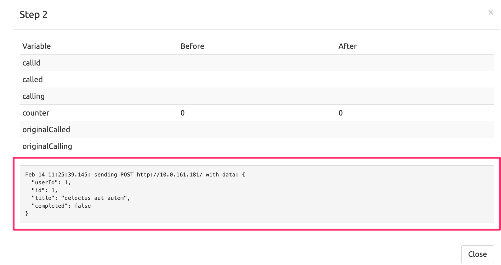
Improved logging -- new in 3.3
The following nodes have improved logging showing the data sent in the request/query. After running a call simulation, mouse over or click the Call Descriptor of the node to view the logging.
HTTP JSON request
ENUM query
DNS query
LDAP query
Example for HTTP JSON request:
HTTP JSON request
Description: Retrieve data from an external web service by sending a HTTP request (get, put, post, deleted, patch) to a JSON API REST endpoint and save the result(s) in a variable(s) by providing the keypath of the data of interest
INFO
A fair knowledge of JSON syntax is required to use such queries. Using postman tool (https://www.postman.com/downloads/)can help testing queries.
Fields:
- Node name: name for this node, showing in the node label in the service logic Build grid
- Description: any additional information, showing below the node name label in the service logic Build grid.
- Method: an HTTP method, any of GET, PUT, POST, DELETE or PATCH
- URL: the address (IP or URL), listening port (default: 5000) and path to data on the distant target of the request
- Timeout (secs): if set, the request is cancelled if not completed before the time has elapsed. Highly recommended, as some queries can take much time to complete.
- Authenticate: if formal authentication is required by the target, check the box to use the username/password set below to get access
- Username: username to use for authentication on the distant webservice
- Password: password to use for authentication on the distant webservice
- Headers: to specify any of the standard HTTP headers and assign it a value, if so required by the target
- Body: the body of the request in JSON syntax, if applicable (empty for GET)
- Store Operations: the JSON path having the queried value and the SRE variable (existing or new) where to store it.
- Skip extraction errors: allows to skip extraction errors and avoid an exception in such a case.
- Status codes: to select HTTP error code(s) requiring a specific exit node (to create and connect in the Build tab)
- Caching: if a time duration range (from 5 secs to 60 mins) is set here, and if the request (same URL and query) has been executed before within that time window, it is searched for in the cache, and data stored are returned as a result without re-executing the external request.
- Outputs:
- not ok
- timeout
- error response: HTTP error not otherwise specified, set specific error codes management with Status codes above.
- failure: error in the JSON path
- (if set with Status code: jump to an additional exit node)
HTTP XML request
Description: Retrieve data from an external web service by sending a HTTP request to an XML API endpoint and save the result(s) in a variable(s) by providing the XML path of the data of interest
This node uses the XPath syntax for the XML Path field in the Store Operations section.
Fields:
- Node name: name for this node, showing in the node label in the service logic Build grid
- Description: any additional information, showing below the node name label in the service logic Build grid.
- Method: an HTTP method, any of GET, PUT, POST, DELETE or PATCH
- URL: the address (IP or URL), optional listening port, and full path to the target XML file located on the external server. Example:
https://www.w3schools.com/xml/simplexsl.xml. - Timeout (secs): if set, the request is cancelled if not completed before the time has elapsed. Highly recommended, as some queries can take much time to complete.
- Authenticate: if formal authentication is required by the target, check the box to use the username/password set below to get access
- Username: username to use for authentication on the distant server
- Password: password to use for authentication on the distant server
- Headers: to specify any of the standard HTTP headers and assign it a value, if so required by the target
- XML Query: a PUT, POST, DELETE or PATCH request in XML format to modify data on the distant server. Depends highly on the distant server configuration, hence no examples can be provided here.
- Store Operations (in XPath syntax):
- XML Path: the path to the data in XPath syntax. Example:
/breakfeast_menu/food[1]/price - Store into: the SRE variable (existing or new) where to store the data.
- XML Path: the path to the data in XPath syntax. Example:
- Status codes: to select HTTP error code(s) requiring a specific exit node (to create and connect in the Build tab)
- Caching: if a time duration range (from 5 secs to 60 mins) is set here, and if the request (same URL and query) has been executed before within that time window, it is searched for in the cache, and data stored are returned as a result without re-executing the external request.
- Outputs:
- success
- error response: HTTP error not otherwise specified, set specific error codes management with Status codes above.
- timeout
- failure: error in the XML Path
- (if set with Status code: jump to an additional exit node)
HTTP GET JSON Query (deprecated)
Use a better alternative node: HTTP JSON request
HTTP GET XML Query (deprecated)
Use a better alternative node: HTTP XML request
HTTP PUT XML Query (deprecated)
Use a better alternative node: HTTP XML request
LDAP query
Using this node requires a fair knowledge of LDAP protocol and its specifications.
Description: Retrieve data from an LDAP server. The data must be queried using a syntax compliant with RFC 4515.
Fields:
- Node name: name for this node, showing in the node label in the service logic Build grid
- Description: any additional information, showing below the node name label in the service logic Build grid.
- Host: IP or hostname of the LDAP server to query
- Port number (if required): default: 389. Can be different if the server administrator has changed the default port, especially if a specific security mode has been activated.
- Security: select the running security mode
- Username: user name with cn= and dc=
- Password: password for that user
- Query base DN: the level in the tree where to start the query, using LDAP syntax
- Timeout (secs): limits the time allowed for query execution if the server is busy or overloaded
- Depth: any of SUBTREE, ONELEVEL or BASE. SUBTREE: the base node plus all nodes below it ONELEVEL: the first level of nodes below the base node, itself and the lower levels excluded BASE: the base node only.
- Filter: to filter entries with an LDAP syntax instruction compliant with RFC 4515
- Search in members: to query also the members within a node
- Attributes fetch: name(s) of the attribute to fetch. The values are stored in the record list (array) specified in the next field.
- Store into records list: array to store the values of the fetched attribute(s)
- Caching: if a time duration range (from 5 secs to 60 mins) is set here, and if the request (same URL and query) has been executed before within that time window, it is searched for in the cache, and data stored are returned as a result without re-executing the external request.
- Outputs: Result of the query and next step:
- success
- not found
- timeout expired
- invalid credentials
- failure
DNS query
Description: Retrieve data from a DNS server. IP address(es) are returned when an FQDN (Fully Qualified Domain Name) is queried; FQDN is returned when an IP address is queried.
Fields:
- Node name: name for this node, showing in the node label in the service logic Build grid
- Description: any additional information, showing below the node name label in the service logic Build grid.
- Query: the FQDN (www.example.com) to get the IP address(es) or the IP address to get the FQDN.
- DNS servers: one or more DNS servers. They are queried in sequence; if not reachable, the process goes to the next server and the non-reachable server is put on a blacklist for one minute.
- Timeout (secs): limits the time allowed for query execution if the server is busy or overloaded
- Store into: array to store the values of the fetched attribute(s)
- Caching: if a time duration range (from 5 secs to 60 mins) is set here, and if the request (same URL and query) has been executed before within that time window, it is searched for in the cache, and data stored are returned as a result without re-executing the external request.
- Outputs: Result of the query and next step:
- success
- timeout expired
- failure
ENUM query
Description: Retrieve data from an ENUM server. Typically, returns a SIP address (sip:name@domain) corresponding to the phone number queried.
Fields:
- Node name: name for this node, showing in the node label in the service logic Build grid
- Description: any additional information, showing below the node name label in the service logic Build grid.
- Phone Number: the phone number linked with the SIP address wanted.
- DNS root: a string telling the server which tree to look for.
- ENUM servers: one or more ENUM servers. They are queried in sequence; if not reachable, the process goes to the next server and the non-reachable server is put on a blacklist for one minute.
- Timeout per server (secs): limits the time allowed for query execution if the server is busy or overloaded
- Store into: array to store the values of the fetched attribute(s)
- Caching: if a time duration range (from 5 secs to 60 mins) is set here, and if the request (same URL and query) has been executed before within that time window, it is searched for in the cache, and data stored are returned as a result without re-executing the external request.
- Outputs: Result of the query and next step:
- success: a NAPTR response matching its regexp was received
- timeout expired: no answer from the ENUM server within the "Timeout per server" period
- failure
- no match: either a NXDOMAIN response or a NAPTR response not matching its regexp was received.
Nemo QoS
Description: Retrieve quality of service counters for several groups of choice from NEMO and store the results.
This node uses specific syntax and parameters depending on customer configuration, including a NEMO instance running in parallel with the SRE. Please contact Netaxis Support for more information.
Read configuration parameter
Description: Read a parameter from the configuration and store it in a variable
This node uses specific syntax and parameters depending on customer configuration. Please contact Netaxis Support for more information.
Date & time
Now
Description: Retrieve the current system time and date and store it in a variable. Mainly used for timestamp comparisons (for example to launch or stop a service having a set timestamp for activation/deactivation, like call forwarding).
Fields:
- Node name: name for this node, showing in the node label in the service logic Build grid
- Description: any additional information, showing below the node name label in the service logic Build grid.
- Store into : the name of the target variable (existing or new) where the output of the operation will be stored.
Add/subtract duration
Description: Add or subtract a number of weeks, days, months, seconds and/or milliseconds to/from a date and store the result in a variable
Fields:
- Node name: name for this node, showing in the node label in the service logic Build grid
- Description: any additional information, showing below the node name label in the service logic Build grid.
- Read from : the name of the source variable (can be the result of a db query)
- Store into : the name of the target variable (existing or new) where the output of the operation will be stored.
- Operation : to add or subtract the defined number of Weeks, Days, Hours, Minutes, Seconds, and Microseconds to or from the value of the Read from variable, and store the result in the Store into variable.
Extract Date/Time parts
URI
The following nodes allow manipulations of a URI (Uniform Resource Identifier). In the SIP context, URIs are made of the following elements:
- a scheme: sip/sips/tel
- a user: <name>
- a host
- optionally, a port.
Example:
sip:001234567890@10.135.0.1:5060;user=phonewhere sip is the scheme, 001234567890 is the user, 10.135.0.1 is the host and 5060 is the port (default SIP port). Additional parameters can be used, separated by ; (user=phone above).
Build SIP URI
Description: Construct a SIP URI with scheme, user part, host part and port and store the result in a variable
Fields:
Node name: name for this node, showing in the node label in the service logic Build grid
Description: any additional information, showing below the node name label in the service logic Build grid.
Build SIP URI: selects a
schemefrom the drop-down list, setsuser,host, and optionallyport(default 5060) and sets a local variable to store the resulting URI string. Several URIs can be built in the same operation.INFO
If the string used in a field matches a variable present in the Call Descriptor, the value of the variable replaces the set string in the URI ('calling' becomes '3210245678').
Next: next node to jump to when done building the string.
Extract SIP URI (deprecated)
Kept for backward compatibility. Will be executed but cannot be used to create a new node. Instead, use Extract URI elements node below.
Extract URI elements
Description: Extract the part of choice of the provided SIP URI and store the result(s) in variable(s)
Fields:
- Node name: name for this node, showing in the node label in the service logic Build grid
- Description: any additional information, showing below the node name label in the service logic Build grid.
- Source URI: the URI string (or variable containing it) to extract elements from.
- Extract scheme into: sets a local variable to store the extracted scheme string
- Extract user into: sets a local variable to store the extracted user string
- Extract host into: sets a local variable to store the extracted host string
To extract specific, additional parameters (;-separated then defined with = in a header field line):
- Extract user parameters into respective variables: check to activate user parameters selection and storage into local variables
- Selective user parameters extraction: selects user parameters to extract (string or variable holding the string value) and sets local variables to store them.
- Extract URI parameters into respective variables: check to activate URI parameters selection and storage into local variables
- Selective URI parameters extraction: selects URI parameters to extract (string or variable holding the string value) and sets local variables to store them.
Manipulate URI elements
Description: Update the part of choice of the provided SIP URI by another value and store the result in a variable
Fields:
- Node name: name for this node, showing in the node label in the service logic Build grid
- Description: any additional information, showing below the node name label in the service logic Build grid.
- Source URI: the URI string (or variable containing it) with elements to manipulate.
- Store result into: the local variable storing the modified URI resulting from the manipulations below.
- Replace scheme, user, host with: string or variable from the Call Descriptor to replace the element present in the Source URI above.
To set, replace or remove additional parameters (;-separated then defined with = in a header field line)
- Set or replace user parameters: name of the user parameter and value to be used to set or replace
- Remove user parameters: name of the user parameter to remove
- Set or replace URI parameters: name of the URI parameter and value to be used to set or replace
- Remove URI parameters: name of the URI parameter to remove
SIP
The following nodes can prepare manipulations of SIP INVITE messages (initial message in a SIP call). Such messages are made of two parts: header and body, as shown below. The header contains information about signalling, each line being a distinctive header (Via:, From:, To:, etc.); the body contains information about the media: IP addresses used and mainly the type of codec to use.
Changes to the SIP INVITE message are not visible in the Service Logic Editor (see Caution below), which only stores the requested processing actions that Kamailio will execute at the very end of the service logic.
[HEADER]

INVITE sip:001234567890@10.135.0.1:5060;user=phone SIP/2.0
Via: SIP/2.0/UDP 10.135.0.12:5060;branch=z9hG4bKhye0bem20x.nx8hnt
Max-Forwards: 70
From: "Calling User" <sip:151@10.135.0.1:5060>;tag=m3l2hbp
To: <sip:001234567890@10.135.0.1:5060;user=phone>
Call-ID: ud04chatv9q@10.135.0.1
CSeq: 10691 INVITE
Contact: <sip:151@10.135.0.12;line=12071>;+sip.instance="<urn:uuid:0d9a008d-0355-0024-0004-000276f3d664>"
Allow: INVITE, CANCEL, BYE, ACK, REGISTER, OPTIONS, REFER, SUBSCRIBE, NOTIFY, MESSAGE, INFO, PRACK, UPDATE
Content-Disposition: session
Supported: replaces,100rel
User-Agent: Wildix W-AIR 03.55.00.24 9c7514340722 02:76:f3:d6:64
Content-Type: application/sdp
Content-Length: 254

[BODY]

v=0
o=151 9655 9655 IN IP4 10.135.0.12
s=-
c=IN IP4 10.135.0.12
t=0 0
m=audio 50024 RTP/AVP 8 0 2 18
a=rtpmap:8 PCMA/8000
a=rtpmap:0 PCMU/8000
a=rtpmap:2 G726-32/8000/1
a=rtpmap:18 G729/8000
a=ptime:20
a=maxptime:80
a=sendrecv
a=rtcp:50025
INFO
Service Logic simulations are executed in the Simulate SIP tab, where a valid SIP INVITE message (like the one above) must be pasted in the Message field for the SIP nodes to have something to process.
WARNING
The nodes below (Extract SIP Header, Remove SIP Header, Add SIP Header, Replace SIP body, Invite Timer, Set From URI, Set to URI) have no immediately visible effect in the Call Descriptors. This is because they don't do more than store the requested actions to be processed by the Kamailio stack (not the SRE) at the very end of Service Logic execution. In other words, the SRE does not visibly modify the SIP INVITE messages: it rather instructs the SIP stack to do so.
If an Extract SIP Header node has succeeded in extracting the User Agent header value into a variable myvar_UA, then a Remove SIP Header node has removed the User-Agent header, and an Add SIP Header node has added a new User-Agent header, the removal and addition will not be visible in the Call Descriptors of the second and third operations, and the value set for myvar_UA by the first operation will remain visible in the Call Descriptor of the last node.
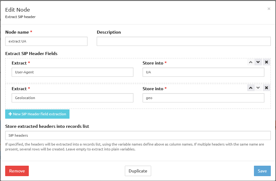
Extract SIP headers - changed in 3.3
Description: Extract SIP headers from the incoming SIP message and store them in a records list (new in 3.3) or plain variables.
Fields:
- Node name: name for this node, showing in the node label in the service logic Build grid
- Description: any additional information, showing below the node name label in the service logic Build grid.
- Extract SIP Header Fields: Select one or more header fields from the drop-down list. Several fields can be selected for processing.
- Store extracted headers into records list: sets or selects a records list or local variables to store the values of the header fields.
- Next: next node if extraction was successful.
- Extraction failure, next node if extraction fails.
Example:
SIP regular expression extraction - new in 3.3
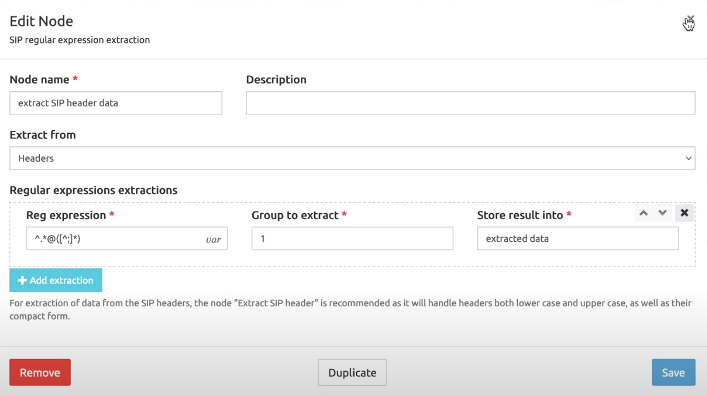
Description: Extract a substring from a SIP message based on a regular expression with regexp capturing groups and store the result in a variable.
Fields:
- Node name: name for this node, showing in the node label in the service logic Build grid
- Description: any additional information, showing below the node name label in the service logic Build grid.
- Extract from: drop-down list to select where to extract a substring from: SIP msg Headers, Body or both.
- Regular expressions extractions: (must be filled in for the node to be created)
Reg expression
Group to extract
Store result into
Example:
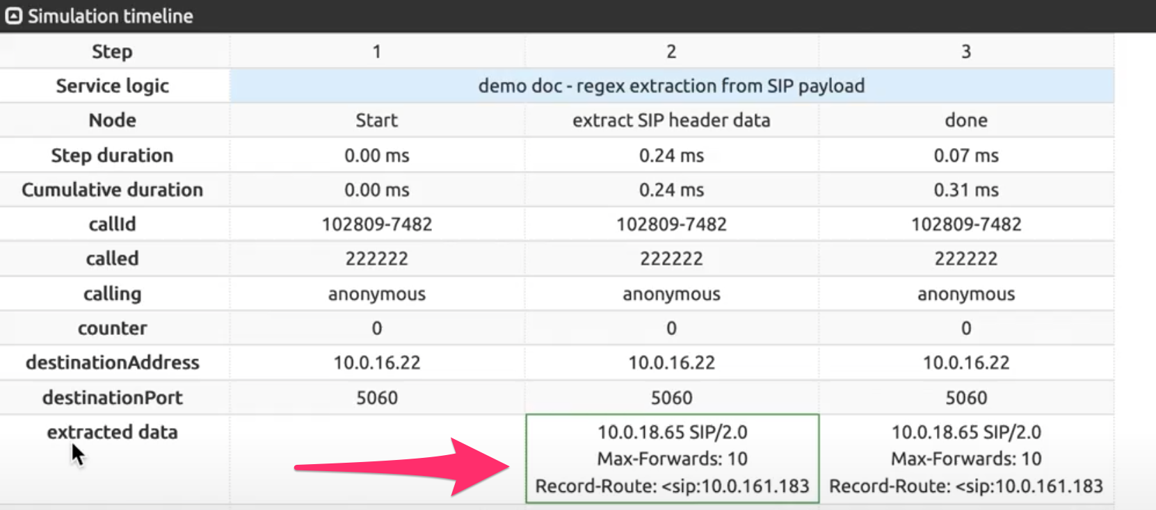
After running a SIP simulation having a SIP message, the Simulation Timeline shows the extracted data:
Add SIP header
Description: Define a SIP header that needs to be added by the SRE before sending the SIP message to the next hop and this by sending the name of the header and its value.
Fields:
Node name: name for this node, showing in the node label in the service logic Build grid
Description: any additional information, showing below the node name label in the service logic Build grid.
Header name: selects one single header field from the drop-down list
Header value: sets the value for this header field (it can be a variable).
INFO
The effect of this header addition operation will not be visible, as the current status of the SIP message after processing cannot be visualized in the Service Logic Editor (see Caution above).
Remove SIP header
Description: Remove a SIP header from the SIP message before sending it to the next hop.
Fields:
Node name: name for this node, showing in the node label in the service logic Build grid
Description: any additional information, showing below the node name label in the service logic Build grid.
Header name: selects one single header field from the drop-down list and removes it and its value from the SIP message.
INFO
The effect of this header removal operation will not be visible, as the current status of the SIP message after processing cannot be visualized in the Service Logic Editor (see Caution above).
Replace SIP header
Description: Defines a SIP header that needs to be replaced/added by the SRE before sending the SIP message to the next hop and this by sending the name of the header and its value. There are two possibilities:
the requested header is not present in the original INVITE: the header is added
the requested header is already present in the original INVITE: the header value is replaced.
Fields:
Node name: name for this node, showing in the node label in the service logic Build grid
Description: any additional information, showing below the node name label in the service logic Build grid.
Header name: selects one single header field from the drop-down list
Header value: sets the value for this header field (it can be a variable).
INFO
The effect of this header removal operation will not be visible, as the current status of the SIP message after processing cannot be visualized in the Service Logic Editor (see Caution above).
Replace SIP body
Description: Modify the body of the incoming SIP message before sending it to the next hop (e.g. SDP).
Fields:
Node name: name for this node, showing in the node label in the service logic Build grid
Description: any additional information, showing below the node name label in the service logic Build grid.
Source regular expression: the string to be replaced in the body, using a regular expression as a search.
Replacement string: the string for replacing the string found in the body, taking groups into account
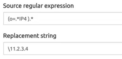
Ignore case: if checked, the search will return the matching string without taking into account the cases ('ip' would match as well as 'IP').
Multiple replacements: if checked, would replace every string found if more than one match is within the same line.
Invite Timer
Description: Set a timer which hits if no final reply for an INVITE arrives after a provisional message was received (e.g. think at scenario's like call forwarding on no reply).
When the SRE relays a SIP INVITE to a destination, using this node sends a command to the Kamailio SIP stack to define a timeout specifying how long the reply can be awaited for. When the timer duration is over, the process considers that this INVITE will never get a reply: the call is terminated and a CDR is generated.
This could be used, for example, with international calls where the connection takes longer to be established.
Fields:
- Node name: name for this node, showing in the node label in the service logic Build grid
- Timer (ms): the duration of the timer in milliseconds
- Next: next node to jump to when the timer has expired.
INFO
Similarly, SIP simulation is not available for this node, see Caution above.
Set From URI
Description: Update the URI part in the From: of the incoming SIP message to the provided string before sending it to the next hop
Fields:
Node name: name for this node, showing in the node label in the service logic Build grid
Description: any additional information, showing below the node name label in the service logic Build grid.
From URI: the new value for the URI in the From: header field, or the name of a variable that contains it (for example built by a Build SIP URI node above).
INFO
The effect of this Set From URI operation will not be visible, as the current status of the SIP message after processing cannot be visualized in the Service Logic Editor (see Caution above).
Set To URI
Description: Update the URI part in the To: of the incoming SIP message to the provided string before sending it to the next hop
Fields:
Node name: name for this node, showing in the node label in the service logic Build grid
Description: any additional information, showing below the node name label in the service logic Build grid.
To URI: the new value for the URI in the To: header field, or the name of a variable that contains it (for example built by a Build SIP URI node above).
INFO
The effect of this Set To URI operation will not be visible, as the current status of the SIP message after processing cannot be visualized in the Service Logic Editor (see Caution above).
Stir/Shaken
Encode JWT
Description: Create a new Json web token
Fields:
- Node name: name for this node, showing in the node label in the service logic Build grid
- Description: any additional information, showing below the node name label in the service logic Build grid.
- Payload to encrypt: data to be encrypted, can be a json object or plain variable
- Private key variable: variable containing the private key used for encryption
- Certificate URL: URL of the certificate to be included in the JWT header
- Expiration Time: set an expiration time (in seconds) in the JWT header
- Store into variable: name of variable to use for storing the token
Decode JWT
Description: Decode an existing Json web token
Fields:
- Node name: name for this node, showing in the node label in the service logic Build grid
- Description: any additional information, showing below the node name label in the service logic Build grid.
- Payload: variable holding the data to be decrypted
- Certificate variable: variable holding the certificate for token verification
- Root certificate variable: optional variable holding the root certificate for certificate validation
- Enable certificate validation: if enabled certificate will be check for validity (recommended)
- Store into variable: name of a variable to use for storing the decoded token, data will be stored as a json object.
Validate JWT
Description: Extract information from a decoded JWT
Fields:
- Node name: name for this node, showing in the node label in the service logic Build grid
- Description: any additional information, showing below the node name label in the service logic Build grid.
- Read token from variable: variable holding the decoded token
- Store attestation level into variable: create (or update) a variable with the STIR/SHAKEN attestation level (A, B, C)
- Store orig/tn into variable: create (or update) a variable with the calling number stored in the token
- Store dest/tn into variable:: create (or update) a record-list variable with the called numbers stored in the token
Generate Identity
Description: Generate an identity header value.
INFO
this node generates the content of the identity header but does not add it to the SIP message. You need to add it explicitly wit the Add Sip Header node.
Fields:
- Node name: name for this node, showing in the node label in the service logic Build grid
- Description: any additional information, showing below the node name label in the service logic Build grid.
- JWT token: variable holding the encrypted token
- Certificate URL: URL of the certificate to be included in the identity header
- Store into variable: name of a variable to use for storing the data of the new identity header
Extract Identity
Description: Extract token and certificate URL from identity header payload. Fields:
- Node name: name for this node, showing in the node label in the service logic Build grid
- Description: any additional information, showing below the node name label in the service logic Build grid.
- Read from variable: variable holding the identity header value (typically this is extracted with Extract SIP headers node)
- Store token into variable: create (or update) a variable with the encrypted JWT token
- Store certificate URL into variable: create (or update) a variable with the URL of the certificate
Add identity header (Kamailio-managed)
Description: add identity header with Kamailio Fields:
- Node name: name for this node, showing in the node label in the service logic Build grid
- Description: any additional information, showing below the node name label in the service logic Build grid.
- Attestation level: variable holding the desired attestation level (A, B, C)
- Certificate URL: variable containing the certificate URL. This URL must be reachable from call processor nodes.
- Private key: variable containing the private key used for encryption
Accounting
When the SRE is operating in proxy mode (managing SIP calls from INVITE to BYE or error), CDRs are generated based on a CDR standard format with default fields. 50 fields are reserved for the system, not all of them being currently used.
For more details about the CDR Standard format, please refer to the Accounting Specs document available from Netaxis Solutions Support team.
More fields can be added to the standard CDR format, to customize the output. These fields can only take the name and value of variables present in the Call Descriptor.
INFO
Simulation of a complete SIP call is not possible in the SLE, which manages only the INVITE part of the call. To test the following nodes, one has to use a SIP call simulator or place a call from a phone.
Append CDR fields
Description: Append an additional field of choice (and its value) to the CDR output stream
Fields:
- Node name: name for this node, showing in the node label in the service logic Build grid
- Description: any additional information, showing below the node name label in the service logic Build grid.
- Elements: one or more instances specified by the names of variables present in the Call Descriptor. Example If a variable «enterprise» and a variable «site» are present in the Call Descriptor (extracted from a SIP INVITE, or set in any manner by a service logic), specifying one element with «enterprise» and a second element with «site» will append a field enterprise and a field site (and their value) after the 50 first reserved fields in the CDR, in the first available positions, i.e. 51 and 52 if no other Append CDR field node has been used before. Using another Append CDR fields node after the first one would append its elements in the next available positions, starting from 53 in our example.
Set CDR fields
Description: Change/update the position of a field in the output CDR
Fields:
- Node name: name for this node, showing in the node label in the service logic Build grid
- Description: any additional information, showing below the node name label in the service logic Build grid.
- Elements: one or more instances specified by the names of variables present in the Call Descriptor. The field Position defines the new position of the element in the CDR output stream, starting at position 51 (with an offset of 50, i.e. after the 50 positions reserved for the system). For example, a value of 5 in the field will set the element position at 55 in the CDR output stream.
Call Admission Control
Call Admission Control allows limiting the number of calls that one or more users can place (outgoing calls) or receive (incoming calls). A record is created in a side Mongo database for every active call matching the parameters defined with the Register Call for CAC node. The Check CAC node is used to verify the number of calls currently recorded as active in the database for a user or group identified by the Aggregation ID.
Note that the Mongo database is only used to manage the CAC counting and is completely independent of the Postgres database used for data administration.
INFO
Simulation of a complete SIP call is not possible in the SLE, which manages only the INVITE part of the call. To test the following nodes, one has to use a SIP call simulator or place a call from a phone.
Register call for CAC
Description: Define based on which parameters the call admission control is administered. When the node is executed, each call matching the parameters is counted and recorded in the database when starting (INVITE), and the record is freed (the number of active calls decreases) when ending (BYE or error code). An automatic cleanup mechanism takes care of calls which would not end (no BYE or no error code received).
Fields:
- Node name: name for this node, showing in the node label in the service logic Build grid
- Description: any additional information, showing below the node name label in the service logic Build grid.
- Aggregation id: an existing variable identifying the user or group of users to consider for CAC. Example: calling. If simultaneous calls are placed from the same calling number, each call will have a distinct record in the database.
- Direction: the direction of the call to consider for CAC. Example: outgoing.
Check CAC
Description: Check the number of calls currently recorded as active by the system. This node usually takes place in the service logic before the Register Call for CAC node, to check if a user or group is still within the limits defined with Max calls or Max outgoing calls and Max incoming calls. If yes, the call is admitted and a Register Call for CAC node can be used to record the call.
Fields:
Node name: name for this node, showing in the node label in the service logic Build grid
Description: any additional information, showing below the node name label in the service logic Build grid.
Aggregation id: same as above
Max calls: the maximum number of calls allowed for a user or group, whatever the direction. An existing database field like max_calls_user can be used instead of a mere integer.
Max outgoing calls: the maximum number of outgoing calls allowed for a user or group. An existing database field like max_calls_user_out can be used instead of a mere integer.
Max incoming calls: the maximum number of incoming calls allowed for a user or group. An existing database field like max_calls_user_in can be used instead of a mere integer.
INFO
The Max conditions are evaluated in sequence, by reading the number of active calls recorded in DB for the Aggregation ID and Direction considered. Empty conditions are ignored. New calls will be admitted as long as the number of recorded calls is below the limits, otherwise, they will be rejected until active calls end and are removed from the DB counting.
Store total calls count into: the number of calls registered for the specific Aggregation id is returned by this counter and stored in the provided variable.
Store total calls percentage into: the percentage of resource consumption (with reference to the provided max calls) registered for the specific Aggregation id is returned by this counter and stored in the provided variable.
Direction: deprecated, not used anymore.
If call is admitted, jump to: usually, a Register Call for CAC node
If call is rejected, jump to: usually, a SIP output node like SIP 403 Forbidden
Additional information
The Call Admission Control can be used at different aggregation levels. A user having «1234» as calling number may have consumed the number of active calls authorized, but the amount authorized for the enterprise the user belongs to may not have been consumed yet. This would allow a different user with calling number «5678» to place or receive calls.
This is achieved by using several Check CAC nodes in sequence, then several Register CALL for CAC nodes so the counting of active calls is done at different levels, for example user, then site, then enterprise.
Misc
Add tag
New in 3.3
Description: add one or more tag for statistics selection and aggregation. Tags filtering or grouping can be added to custom dashboards, for reference see Admin Guide.
Fields:
- Node name: name for this node, showing in the node label in the service logic Build grid
- Description: any additional information, showing below the node name label in the service logic Build grid.
- Name: name of tag
- Value: value of tag
Evaluate expression
Description: Evaluate a Python expression on the local system before continuing to the next node. Only constants are admitted, variables or placeholders are not.
Fields:
- Node name: name for this node, showing in the node label in the service logic Build grid
- Description: any additional information, showing below the node name label in the service logic Build grid.
- Expression: a simple Python expression with constants and operators (variables not admitted).
- Store into: name of a variable to use for storing the result of the expression. Note that the content of the variable can be seen in the Simulate Call tab when mousing over the 'evaluate expression' node step number (or subsequent nodes) after Run.
Render template
This node is used to build a string from a JINJA (python templating language) rendering template (see https://jinja.palletsprojects.com/en/2.11.x/). From the template designed, local variables can be accessed like this: ; one can also use conditions etc. from within the templating language.
Description: Define a JINJA template and replace its parameters by variables of choice and store the result in a variable
Fields:
- Node name: name for this node, showing in the node label in the service logic Build grid
- Description: any additional information, showing below the node name label in the service logic Build grid.
- Template: the text of the template according to the JINJA syntax.
- Store into: name of a variable of choice to store the string resulting from the designed rendering template.
Shell command
Description: Execute a shell command on the local system.
WARNING
There is no validation or rollback for the execution of the command. To be used with extreme care.
Fields:
- Node name: name for this node, showing in the node label in the service logic Build grid
- Description: any additional information, showing below the node name label in the service logic Build grid.
- Shell command: one or more (separated by ; ) shell commands to execute
- Strip \r or \n characters at end of command output
- Store into: name of a variable to use for storing the output of the executed command(s). Note that the content of the variable can be seen in the Simulate Call tab when mousing over the 'shell command' node step number (or subsequent nodes) after Run:

- Outputs:
- next node if execution succeeds
- next node if execution fails
Generate alarm
Description: Generates an alarm, which will show both in the Alarms screen and via SNMP traps.
Fields:
- Node name: name for this node, showing in the node label in the service logic Build grid
- Description: any additional information, showing below the node name label in the service logic Build grid.
- Type:it's the type shown in the Alarms tab, allowing for search based on type.
- Severity: Info, Warning, Minor, Major, Critical
The alarms generated by this node are never cleared: this is left as a manual action or by the Clear Alarm node. If several alarms are generated using this node and have the same Type and Description, they will be grouped within the Alarms list.
Increment custom counters
Description: Allows incrementing a counter with a given name by a given value. The counter is expressed in terms of hits/sec., in the same way, all the metrics in the Dashboard tab Stats:Counters are shown. This is useful for example to have the dashboard display the number of calls/sec. tagged in a certain way. Once created with the Service Logic node, the custom counter is shown in the Dashboard tabs Stats:Counters and Stats:Performance.
Fields:
- Node name: name for this node, showing in the node label in the service logic Build grid
- Description: any additional information, showing below the node name label in the service logic Build grid.
- Name : the counter's name
- Value : the counter's increment value
Send syslog message
Description: Send a message to a remote syslog server. The message will be appended to an existing syslog text file.
Fields:
- Node name: name for this node, showing in the node label in the service logic Build grid
- Description: any additional information, showing below the node name label in the service logic Build grid.
- Address: IP Address of the remote syslog server
- Port: 514 --- default port on the syslog server for listening the syslog messages
- Facility: information about the origin of the message. How the message will be handled is determined by a configuration file designed by the server administrator: send a mail, write to log file <filename>, etc.
- Log level: criticality level (any of: debug, info, warning, error, critical)
- Message: text of the message. Optionally, values stored in variables from the Call Descriptor can be added to the text using a placeholder [variable_name]. See Placeholder mechanism for more information.
Send Email
Description: Send an email with a configurable destination, subject and message via an SNMP server of choice.
Fields:
- Node name: name for this node, showing in the node label in the service logic Build grid
- Description: any additional information, showing below the node name label in the service logic Build grid.
- SMTP Configuration: information provided by the mail service provider
- Recipients: e-mail addresses of the message recipients
- Subject, Message: the title and text of the message. Placeholders are admitted in both fields.
Clear Alarm
Description: Clear an alarm, if the type prefix matches an existing custom alarm, previously triggered by a Service Logic and still active in the system.
Fields:
- Node name: name for this node, showing in the node label in the service logic Build grid
- Description: any additional information, showing below the node name label in the service logic Build grid.
- Type prefix : the prefix part of a custom alarm that matches an active alarm. For example, if an active alarm has the type = "service1.status.status1", the clear alarm with a type prefix = "service1.status" would clear this alarm.
Output Nodes
SIP
SIP Relay
As output at the end of a service logic providing a destination for a SIP INVITE, this node sets the SIP URI to use and specifies optional processing (alternative destination, recursion) when a SIP error occurs.
Description: Provide a new request URI and proxy the INVITE to the next hop
Fields:
- Node name: name for this node, showing in the node label in the service logic Build grid
- Description: any additional information, showing below the node name label in the service logic Build grid.
- New SIP R-URI: name of the variable storing the new URI at the end of the service logic process, usually in the format
sip:username@domain(domainbeing an IP address or domain name) - Destination host: fixed IP address (and optionally port, for example, non-standard port 5061) to be used alternatively if the destination IP address stored in the variable is not to be used. If empty, the SIP URI from the above variable is used.
- Recurse call on SIP error: when checked, if a SIP error is returned (for example 503 Service Unavailable), a new iteration of the service logic is executed with the execution counter variable incremented by 1.
- Reply status codes to intercept (regex): when not empty all SIP responses with code matching the regular expression will be intercepted and the service logic for SIP reply will be executed for each response.
- Persist call descriptor on recursion or reply handling: when checked, the values of the variables stored in the Call Descriptor at the end of the previous iterations are kept at the start of the next one. This prevents the service logic from re-executing DB queries already done: the results of the queries (for example, multiple destinations stored in a record list) remain available for the next execution of the service logic. The counter is incremented (Recurse call option above), the next record in the record list will be used without having to re-query the DB(s). See also the explanation of Persist Call Descriptor option in SRE Service Logic Editor Manual / Simulate SIP tab section (cross-references to other documents are currently not implemented).
SIP Relay with forking
New in Rel 3.3
As output at the end of a service logic providing a destination for a SIP INVITE, this node sets the SIP URI to use and specifies optional processing (alternative destination, recursion) when a SIP error occurs.
Description: Provide a list of new request URIs and proxy the INVITE to all R-URIs in parallel.
Fields:
- Node name: name for this node, showing in the node label in the service logic Build grid
- Description: any additional information, showing below the node name label in the service logic Build grid.
sip:username@domain(domainbeing an IP address or domain name) - Destination host: fixed IP address (and optionally port, for example, non-standard port 5061) to be used alternatively if the destination IP address stored in the variable is not to be used. If empty, the SIP URI from the above variable is used.
- Records list: new R-URIs will be read from this records list
- R-URI column name:name of the column of the record list that contains new R-URIs.
- Recurse call on SIP error: when checked, if a SIP error is returned (for example 503 Service Unavailable), a new iteration of the service logic is executed with the execution counter variable incremented by 1.
- Reply status codes to intercept (regex): when not empty all SIP responses with code matching the regular expression will be intercepted and the service logic for SIP reply will be executed for each response.
- Persist call descriptor on recursion: when checked, the values of the variables stored in the Call Descriptor at the end of the previous iterations are kept at the start of the next one. This prevents the service logic from re-executing DB queries already done: the results of the queries (for example, multiple destinations stored in a record list) remain available for the next execution of the service logic. The counter is incremented (Recurse call option above), the next record in the record list will be used without having to re-query the DB(s). See also the explanation of Persist Call Descriptor option in SRE Service Logic Editor Manual / Simulate SIP tab section (cross-references to other documents are currently not implemented).
Proxy SIP Error
This node has no parameters: it simply sends back to the call originator the last SIP error sent to SRE by the network instead of an SRE specific output like a SIP error node (see below SIP 301 to 607).
Description: Proxy the last SIP error received from the network to the call originator.
Fields:
- Node name: name for this node, showing in the node label in the service logic Build grid
- Description: any additional information, showing below the node name label in the service logic Build grid.
Example:
A service logic has been iterated 3 times (counter = 2) and no destination has been found reachable after the 3 iterations. Instead of using specific SIP error nodes as ultimate outputs for this logic, this node simply returns to the call originator the last SIP error sent to SRE by the network, whatever the particular reason for which no destination is reachable.
Recurse
Description: Recurse, i.e. execute the next iteration of the service logic, triggered at the reception of an error message from the network, or based on the results of conditions in the course of the current iteration (see example below).
Fields:
- Node name: name for this node, showing in the node label in the service logic Build grid
- Description: any additional information, showing below the node name label in the service logic Build grid.
- Request URI: name of the variable storing the destination URI to be used by the service logic on recursion, usually in the format
sip:username@domain(domainbeing an IP address or domain name)
Example:
At some step in its course, the service logic checks the status of the SIP Agents under monitoring (see SRE Admin Guide for details). If a SIP Agent is UP, the set destination is reachable and a SIP Relay output node is specified as the next hop. If no SIP Agent is UP (all DOWN or TRYING), the set destination is not reachable: to avoid sending a useless INVITE to the network, this Recurse output node is used as the next hop, with an alternative destination specified in Request URI. This causes the service logic to recurse, i.e. to execute a new iteration with the counter incremented by 1 to try and find an available SIP Agent with a reachable destination.
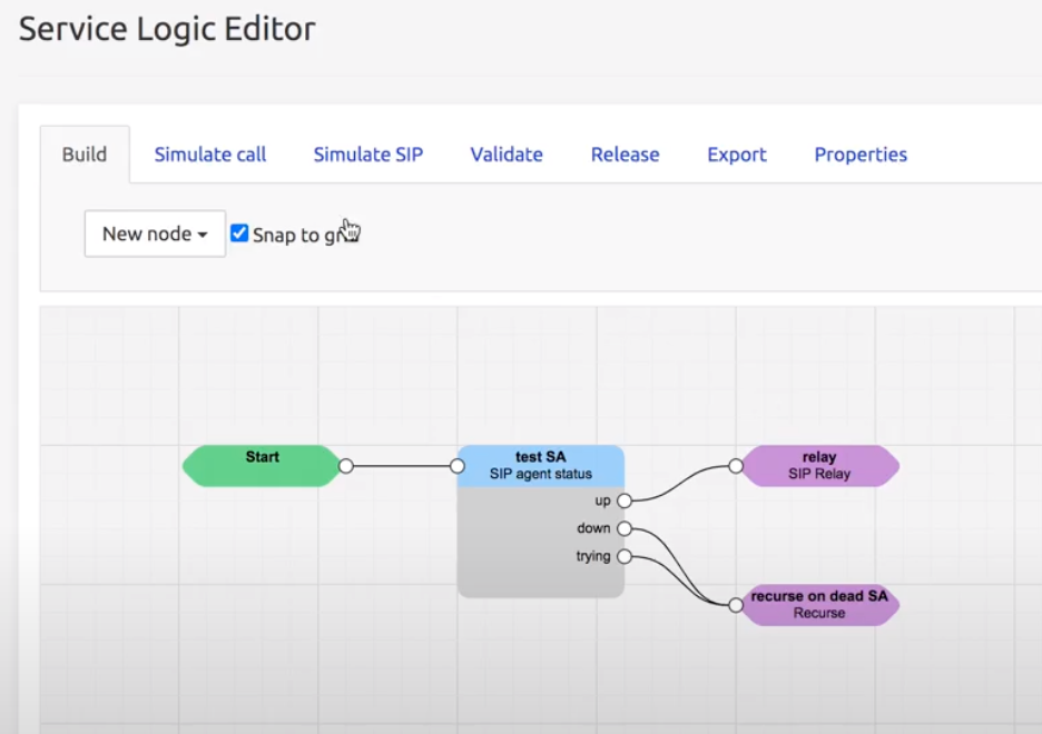
Custom SIP Response - new in 3.3
This node allows defining a customized SIP response by specifying both the response code and the reason header.
SIP 301 to 607
All these nodes correspond with standard SIP messages and codes, described in the RFC3262 document and therefore not further described here.
They are sent back to the call originator based on the results of the service logic processing.
An alternative output is the Proxy SIP error node above, which sends back the last error received from the network instead of returning a more specific error determined by the service logic results.
SIP Registrar
The SIP Registrar nodes are used to authenticate REGISTER or INVITE SIP messages.
Please refer to the Training document Registrar for SRE for detailed explanations. This document can be requested from Support Team.
Authenticate
Description: after an initial REGISTER without an authentication header (and authStatus = 0), this node challenges the SIP client to provide a password authenticating it for further processing.
Fields:
- Node name: name for this node, showing in the node label in the service logic Build grid
- Description: any additional information, showing below the node name label in the service logic Build grid.
- Password: the value of a variable retrieved through a DB request «fromUser» providing the SIP client identity and credentials stored in DB. This is the value the SIP Client has to provide on REGISTER. Can be in plain text; if the Password in HA1 format control is checked, the password is using HA1 format, i.e.
HA1 = MD5(username:realm:password). This allows storing the password in DB in a secure way (the original readable password being unknown and not stored).
Save in Location Service
Description: When the authentication is successful, this node sets the authStatus variable to 1 and stores the SIP client location information in DB.
Fields:
- Node name: name for this node, showing in the node label in the service logic Build grid
- Description: any additional information, showing below the node name label in the service logic Build grid.
Lookup in Location Service and Relay
Description: this node is used to relay an INVITE to an endpoint that has been registered (and saved in Location Service). Based on the R-URI provided, it looks for the location information in DB and if found, relays the INVITE to the location of the registered endpoint.
Fields:
- Node name: name for this node, showing in the node label in the service logic Build grid
- Description: any additional information, showing below the node name label in the service logic Build grid.
- New SIP R-URI: the URI of the INVITE destination.
- Recurse on SIP error: when checked, if a SIP error is returned, a new iteration of the lookup is executed with the execution counter variable incremented by 1 to select, for example, an alternative destination (Voice Mail, Send e-mail...).
ENUM
The E.164 Number to URI Mapping (ENUM) standard uses special DNS record types to translate a telephone number into a Uniform Resource Identifier (URI) or IP address.
This particular process must be part of a service logic using the ENUM interface, where the SRE acts as an ENUM server.
An external equipment from the VoIP network launches, as a client, an ENUM query towards the sre-enum-process. The query has an enumNumber value (phone number value) and an enumQuery value (the phone number reversed and the DNS root, i.e. the NAPTR format).
The sre-enum-process (ENUM server) answers the query with one or more URIs or IP addresses matching the original phone number value. The answers can be formatted and edited as described below, and are returned to the external client origin of the query.
ENUM answer
Description: Formats and provides one or more URIs or IP addresses matching an ENUM query based on a phone number.
Fields:
- Node name: name for this node, showing in the node label in the service logic Build grid
- Description: any additional information, showing below the node name label in the service logic Build grid.
- Answers: one or more set of parameters formatting the URIs or IP addresses from the query. Parameters are:
- Order: a primary order criterion for using the answers
- Preference: a second preference criterion for answers having the same order criterion. Allows load balancing between answers.
- Flags: sets the type of answer (depends on the DNS protocol).
- Source regex: manipulation of the string returned by the ENUM server, for example, to capture a part of the string using ().
- Destination regex: manipulation of the destination string, for example to transform it into
\1@domainwhere@domainis the result of a DB query.
INFO
In the Service Logic Editor, the Simulate ENUM tab is masked to avoid too many tabs in the interface. It can be restored through an easy operation to be performed by Netaxis Support team.
ENUM multi-record answer
Description: this output node allows storing all ENUM answer records into a record list, and indicates the relevant columns in the node.
Fields:
- Node name: name for this node, showing in the node label in the service logic Build grid
- Description: any additional information, showing below the node name label in the service logic Build grid.
- Record list : the name of the record list containing the ENUM answers parameters.
- TTL column name : the name of the column in the record list containing the ENUM Answer TTL.
- Order column name : the name of the column in the record list containing the ENUM Answer Order.
- Preference column name : the name of the column in the record list containing the ENUM Answer Preference.
- Flags column name : the name of the column in the record list containing the ENUM Answer Flags.
- Service column name : the name of the column in the record list containing the ENUM Answer Service.
- srcRegEx column name : the name of the column in the record list containing the ENUM source (matching) Regular Expression.
- dstRegEx column name : the name of the column in the record list containing the ENUM Answer destination (translation) Regular Expression.
ENUM response NXDOMAIN
This output node is used to provide an NXDOMAIN (No Matching found) response to the ENUM client.
Fields:
- Node name: name for this node, showing in the node label in the service logic Build grid
- Description: any additional information, showing below the node name label in the service logic Build grid.
HTTP
HTTP response
This node allows specifying the content-type and body of the response of type 200 OK which will be returned in case of execution of a service logic for the HTTP interface.
Fields:
- Node name: name for this node, showing in the node label in the service logic Build grid
- Description: any additional information, showing below the node name label in the service logic Build grid.
- Content-type: the MIME type (two-part identifier for file formats and format contents) of the Body.
- Body: the content of the response
Examples
| content-type | body |
|---|---|
| text/plain | toto |
| text/html | <html><body></body></html> |
| application/json | {"a": 3} |
Probing
Agents List
This node takes as input a record list of peers to send customized SIP OPTIONS to each peer. The required columns are:
Name (mandatory)
Address (mandatory)
Port (optional, default=5060)
Transport (optional, default=UDP)
Request-URI (optional, only set it if you need a specific one)
To-URI (optional, only set it if you need a specific one)
From-URI (optional, only set it if you need a specific one)
The result of the SIP OPTIONS polling is visible in the Dashboard tab SIP Agents, as it happens with the nodes configured in the tab System > SIP Agents Monitoring (default SIP OPTIONS).
CDR Post-processing
Dedicated Service Logics can now be defined to post-process the standard type of CDRs that the SRE itself produces. Such type of SL (named CDR post-processing logic) will run after a call is closed, that is on "Stop" type of CDRs, to perform actions like applying a rating by indicating e.g. the final cost of the call, or writing other useful information taken from the original CDR into the SRE internal DB or to an external repository via API, and possibly other useful actions. This is sometimes also referred to as Rating Engine or Light Rating Engine.
The CDR post-processing nodes require the "accounting" license.
This feature comes with a Simulate CDR option in the Service Logic. The user can provide a CDR in input and verify the result of post-processing.
Output CDR Row
When using this node, you have to define exactly the output columns, so that a brand new CDR is produced only containing the columns defined here.
Skip CDR row
This node prevents the production of a new CDR upon execution of this service logic.
Example: the SRE produces 10k standard CDRs , of which 7k inbound and 3k outbound, and you want to post-process only the inbound ones... the "skip cdr row" node can be used to say in the SL: if this cdr is for an outbound call, do nothing (don't produce a post-processed cdr).
Start Node
Description: the starting node of any service logic, automatically placed on the Build grid at service logic creation.
Fields:
- Node name: name for this node, showing in the node label in the service logic Build grid
- Description: any additional information, showing below the node name label in the service logic Build grid.
Exit node
Description: Exit the current service logic and give back the execution control to the parent service logic
Fields:
- Node name: name for this node, showing in the node label in the service logic Build grid
- Description: any additional information, showing below the node name label in the service logic Build grid.
